What is SOLIDWORKS Circuit Works?
Circuit Works is a translator bridge for SOLIDWORKS. It allows SOLIDWORKS to open files produced by Electrical CAD software for Printed Circuit Board (PCB) design. Upon opening the file, SOLIDWORKS will create an assembly model of the PCB. Circuit Works also allows SOLIDWORKS to save changes back to files to be imported in the electrical design software. Components on the PCB can be moved and the file exported to allow the electrical designers to see possible changes.
What is SOLIDWORKS CircuitWorks Lite?
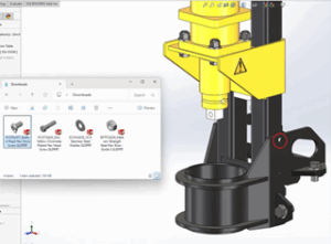
CircuitWorks Lite is a version of CircuitWorks that is included with all levels of SOLIDWORKS. It is accessed via the File -> Open menu (dialog box). When you switch the file type in the Open dialog box to the “IDF” option, you are using CircuitWorks Lite. There are a few limitations to this Lite version, namely:
- cannot export an IDF file (import only)
- creates a part model with features (extrusions) not an assembly
- does not import notes or annotations or keep outs
- cannot use a library of parts
- inefficient for PCB’s with more than 500 components
What is the IDF standard?
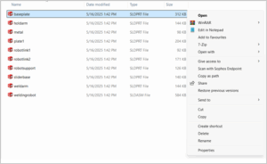
The files used by CircuitWorks are referred to as “IDF” files. IDF is an acronym for Intermediate Data Format which is an open (not proprietary) file format. There have been a few revisions to the IDF file format, the IDF 2.0 & 3.0 standards are very common while the IDF 4.0 standard is slowly being adopted. The 2.0 & 3.0 standard files actually do not have an extension of “.IDF”, and for one mode there is actually 2 files that must have the same name (but different extension). They typically have extensions such as “.emn” & “.emp”, “.lib” & “.brd”. The IDF 4.0 files are much more complex, contain much more information than the earlier file types and actually use the “.IDF” file extension and there is only one file. CircuitWorks can also open files from the software “PADS” which use the “.asc” extension.
Why implement Circuit Works?
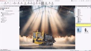
Historically Electrical & Mechanical departments work separately when designing electro-mechanical products. Electrical designs the functionality of the circuits and designs the PCB (the inside). Mechanical designs the shape or form of the product and the method of production (the outside). Your lead time can be reduced as the Mechanical and Electrical teams can work together to create the product. Prototypes, drawing checking and meetings can be reduced as the model files are shared back and forth as the product evolves. This sharing of information will allow for efficient and accurate design, the PCB “fits” neatly inside housing. Button location and screen position can all be optimized to suit mechanical or electrical constraints. The finished SolidWorks model can then be used for thermal analysis (eg. Flow Simulation), visualization and sales.
What does Circuit Works not do?
- Does not open or edit “ladder logic” diagrams (programming schematic) or electrical schematics.
- Does not design PCB trace paths (routing for traces to avoid crossing)
- Does not analyze thermal aspects of design (heating/cooling)
How do I get the product?
A license of CircuitWorks is included with SOLIDWORKS Premium. When the add-in is enabled a CircuitWorks menu will be visible in SOLIDWORKS. Access the commands thru this menu.
Watch online Demo below and learn more at
https://www.solidworks.com/sw/products/3d-cad/electrical-mechanical-cad-interchange-circuitworks.htm