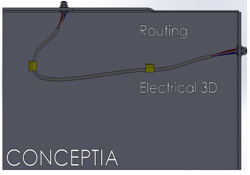
In this article, I will tackle a frequently asked question I encounter while assisting clients with electrical design: What sets SOLIDWORKS Routing apart from SOLIDWORKS Electrical 3D? nothing but we analysed here SOLIDWORKS Electrical 3D vs Routing.
SOLIDWORKS Electrical 3D and SOLIDWORKS Routing utilize the same underlying technology to create route geometry in SOLIDWORKS assemblies, resulting in a similar look and feel. However, in order to identify their differences, it is necessary to analyze certain aspects of how a route is defined.
Geometrical Definition
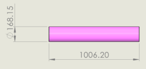
In SOLIDWORKS, the initial step in creating a route is to define the physical geometry of the cable. This mainly entails identifying the specific path that the cable/wire will traverse within the assembly. Additionally, there is the option to assign a diameter to each segment, which can be beneficial in resolving any potential clashes or obstructions between the cable and its surroundings.
Electrical Definition
The next step involves assigning properties to the wire and cable parts within the route. This includes specifying the pin-to-pin connections between connectors in the assembly. It is important to note that certain assignments can affect the geometric definition of the cable, such as the diameter and color of the route segments.
Both SOLIDWORKS Electrical 3D and SOLIDWORKS Routing provide the capability to define these two aspects of the cable/wire, but they approach it differently. To better understand the process, let’s examine how a basic cable/wire can be created using each product.
SOLIDWORKS Routing
- To begin the route assembly, you can initiate it by right-clicking on a connector and selecting the option “Start Route.” Once you are in the route assembly, you have the ability to add more connectors by right-clicking on them and choosing the option “Add to Route.”
2. Wire “stubs” are generated automatically at each pin of the connectors. To connect the stubs of one connector to another, you can right-click on the endpoint of a stub and choose the option “AutoRoute.” From there, you can select either another stub endpoint or an intermediary component like a wire clip/tie to assist in guiding the cable through the assembly to its intended location. This process will establish the main trunk of the cable.
3. To determine the locations where breakouts should occur, such as near the back of a connector, you can right-click on the main trunk and select the option “Split Route.” This allows you to define the specific points where the route should be split. Additionally, you can utilize the AutoRoute command to connect additional pins to the route through this split point.
4. If desired, you have the option to set the nominal diameter of important sections of the route by right-clicking on a segment and choosing “Route Segment Properties.” However, please note that this value will be replaced if a wire or cable with specific diameter properties is assigned.
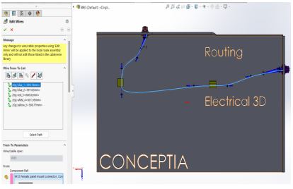
5. The electrical connection parameters can be defined by selecting the “Edit Wires” command. You can assign wires and cables to the route, and establish their pin-to-pin connections using the paths that were created in the previous steps.
SOLIDWORKS Electrical 3D

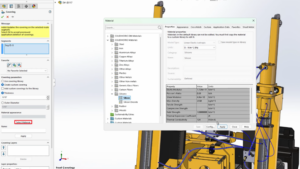
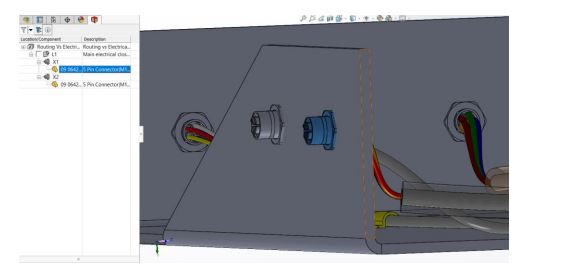
- To initiate the routing process, it is necessary to define the routing components by associating the connectors in the assembly with references from the 2D Schematics Electrical Project. Associate the component by Right clicking the component in the Electrical Management tab and select the component in the assembly
2. Begin by creating a 3D sketch path that follows the desired route, ensuring it is closest to the origin and destination of the component. Then, convert this 3D sketch path into an EW (Electrical Wiring) path by selecting the 3D Sketch.
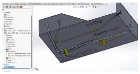
3. To begin the route assembly, use the “Route Harnesses/wires” command and choose the specific project’s harness/components to start the route. There is an option to either route automatically or manually for more precise control. If manual routing is chosen, the route path can be completed using the same method as with SOLIDWORKS Routing, utilizing the AutoRoute command.
4. When using the “Route Harness” command, the electrical connection parameters and wire/cable assignments are imported directly from the schematics. As a result, the route parameters will automatically adjust their graphical properties, such as diameters and colors, to reflect these imported properties once a valid route path has been established.
Key Benefits of SOLIDWORKS Routing & SOLIDWORKS Electrical 3D
Both solutions have the advantage of being fully integrated into SOLIDWORKS assemblies. This integration allows for a more efficient and streamlined procedure compared to spline sweeps.
In SOLIDWORKS Routing, users have the ability to develop libraries with commonly used elements. The electrical parameters in this tool are manually defined by the mechanical user. SOLIDWORKS Routing is particularly beneficial in situations where there is a low volume of cables or when only the physical definition is needed.
In SOLIDWORKS Electrical 3D, libraries are linked with the Electrical designers’ library. This tool allows for schematic-driven wire/cable assignments and pinouts, eliminating the need for manual data entry by the mechanical user. SOLIDWORKS Electrical 3D is particularly well-suited for situations that involve a low to high volume of cables, where both the physical and electrical definition is required.
In today’s dynamic market landscape, industries are constantly seeking tailored solutions that align seamlessly with their unique operational needs. Expanding beyond the confines of traditional approaches, the emphasis now lies in identifying specialized tools that cater to specific vertical sectors. You can explore how the SOLIDWORKS Electrical Suite stands out as a robust choice across diverse industries and verticals Conclusion.
After gaining an understanding of the operational distinctions between the two tools, it is important to address the question: “Which tool is the most suitable for my needs?” The answer to this question will depend on the specific requirements of each business. However, for an informed decision, it’s recommended to analyze and compare the key benefits of each tool. Contact Conceptia Konnect for a detailed technical demo on electrical 3D.