In a rapidly evolving digital landscape, where connectivity and seamless data exchange are paramount, Radio-Frequency Identification (RFID) stands out as a transformative technology reshaping industries and redefining the way we interact with the world. From supply chain management to retail, healthcare, animal tracking and beyond, RFID has emerged as a powerful tool for efficient identification, tracking, and data management.
RFID systems use various types of antennas depending on the application and the specific requirements of the RFID system. The choice of antenna plays a crucial role in determining the performance of the RFID system, including read range, reliability, and overall effectiveness. Dipole, Loop, and circular/Linear polarized patch antennae are the commonly used RFID antennae.
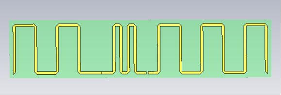
One of the best illustrations of an RFID antenna is a meander dipole antenna, which is modelled in CST Studio Suite software, as shown in Fig.1
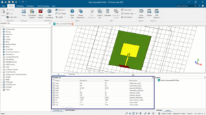
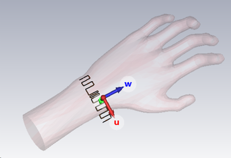
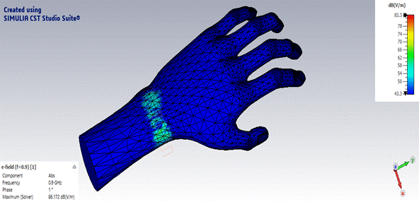
The antenna is configured to operate at a 900MHz frequency. CST Studio Suite software offers various solvers and modelling choices, allowing for the adjustment of parameters according to specific needs. Parametric analysis can enhance simulation results, and if necessary for RFID applications, biological models from the CST library (Voxel data) can be imported and analysed the results by placing the antenna on the voxel model, as shown in Fig. 2
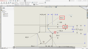
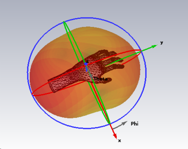
Different types of simulation results, such as S11, VSWR, Gain, Directivity, bandwidth, beamwidth, E-field, H-field, surface current, etc., can be observed using the 1D, 2D and 3D radiation patterns. The E-field and far-field polar plots, along with the structure, can be observed as shown in Fig.3 and Fig.4
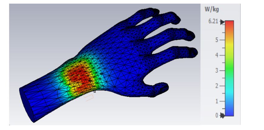
The Specific Absorption Rate (SAR) is a measure of the rate at which energy is absorbed by the human body when exposed to a radiofrequency (RF) electromagnetic field. It’s important to note that SAR values are subject to regulatory standards and guidelines, and devices must undergo testing to ensure compliance with these standards before they can be legally sold in many countries. SAR is typically expressed in watts per kilogram (W/kg). The SAR value of the Meandering dipole can be calculated by CST Studio Software, as shown in Fig 5.
The exploration of the design and analysis of RFID antennas using CST has provided valuable insights into the intricate world of wireless communication. Engineers and researchers must embrace advanced tools like CST to stay at the forefront of antenna development, ensuring that RFID systems continue to evolve and meet the ever-expanding demands of our interconnected world.
The world of RFID antenna design awaits, and with CST Studio Suite, the future is brighter than ever before! Contact us to explore the possibilities of CST Studio Suite for your RFID antenna design needs. Our team is ready to assist you in leveraging the full potential of this exceptional software.