What is Drop test analysis in SOLIDWORKS Simulation
Drop test analysis in SOLIDWORKS Simulation is used to evaluate the effect during the impact of a part or an assembly with a flexible or rigid planar surface. The typical application is done by dropping an object on the floor and hence the name. The program calculates impact and gravity loads automatically.
SOLIDWORKS Simulation Professional module is used to replicate the drop test. A drop test study is a specific type of dynamic analysis used to model the impact force of a short time duration event.
Below are the steps to simulate drop test analysis in SOLIDWORKS Simulation
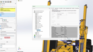
Drop test analysis – Step 1 – Apply Materials
Linear-elastic or elastoplastic material can be defined for the drop test. For most simulation studies, we use linear elastic materials. In a drop test, loss of energy is normally occurring due to damping, friction, or plastic deformation. SOLIDWORKS Simulation is capable of using elasto-plastic material to make the model a little more realistic. The two additional necessary parameters for the elasto-plastic material model in the drop test are yield stress and the tangent modulus.
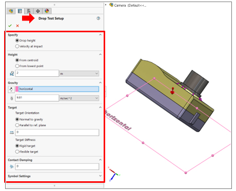
Drop test analysis – Step 2 – Drop test Set-up
In Drop Test Setup Property Manager, we define the drop height, the acceleration, orientation of the impact plane, and target stiffness. The drop height is the height from which the model is dropped from rest. The orientation of the impact plane may be normal to gravity or parallel to a reference plane.
- Normal to gravity when the impact plane is normal to gravity.
- Parallel to Ref. plane when The impact plane is parallel to the selected reference plane. For target orientation reference, select a reference plane. Available only when Parallel to ref. plane is selected.
- Friction Coefficient sets the coefficient of friction between the model and the impact plane.
The body moves in the direction of gravity as a rigid body until it hits the rigid plane. The program determines the region of impact based on the direction of the velocity at impact and orientation of the impact plane. The program calculates the velocity (V) at impact from: V = (2gh)1/2. As an alternative to the drop height, we can also define the velocity at impact. The target stiffness can be a rigid target or a flexible target (i.e. Elastic floor). Additionally, we can specify contact damping. Due to numerical instabilities in the solution procedure, an energy imbalance can be occurring and the solution would fail to converge. In these instances, users can enter some contact damping to potentially allow for the balance of energy and add more stability to the solution. It is recommended that this option is only used if such an energy imbalance occurs since it is only providing numerical stability, not “real” damping.
No other loads or restraints are allowed and no rotations are considered until the initial impact occurs.
Drop test analysis – Step 3- Define Result Options
When we set up our result option, we may want to log data from the simulation at certain predefined points on the model. In the SOLIDWORKS Feature Manager design tree, right-click sensors and select add sensors to create workflow-sensitive data on predefined locations. Under the result option, we can set solution time after impact which is a period of real-time for which the program calculates the response starting from the moment of first impact. If you specify a drop height, the solution time does not include the period of free fall of the body. While there is no limit on solution time after impact, a longer solution time requires a longer time to run the analysis.
We can set ‘save result from starting time from’ for start saving results. Enter zero to start saving results immediately after the impact. Set No. of plots (i.e. solution time is divided by No. of plot and the full results are saved only for those intervals) and No. of graph steps per plot. The total number of data points for each graph is equal to the number of plots time the number of graph steps per plot.
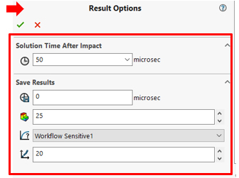
Input parameters in the Result Options Property Manager.
Drop test analysis – Step 4 – Mesh the Model
Create a mesh that will obtain accurate results for the simulation. If you are predicting a large displacement or high-stress concentration, apply mesh control as well as a curvature-based mesh to accurately take small features into account.
Drop test analysis – Step 5 – Run the analysis and Post Process the results
After the solution is completed, analyze the results of the study. Animate the stress and displacement plots to get an idea of the behavior after impact. To track data at specific points, add sensors to the model and track them with a time history graph. This analysis will not predict the separation of bonded components due to impact, instead, it can be used to evaluate the possibility of such a scenario. The maximum stresses can be used to predict material failure and contact forces to predict the separation of components
SOLIDWORKS Simulation uses an Explicit method for solving Drop test analysis and despite the fact that solving Drop test involves capturing results within microseconds of impacts with thousands of small-time steps, with SOLIDWORKS, it’s quick and simple for users to set up and study drop test performance of designs.