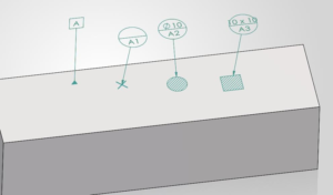
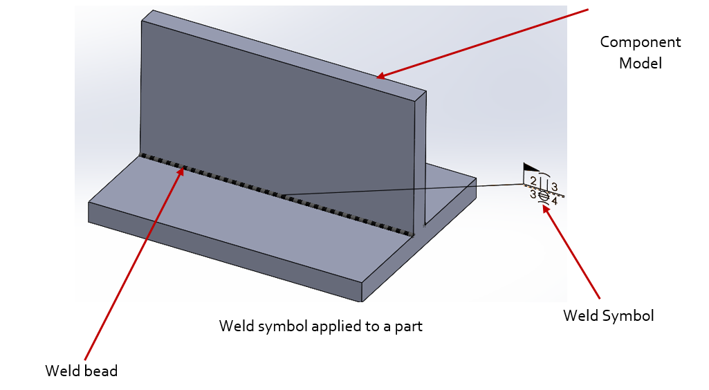
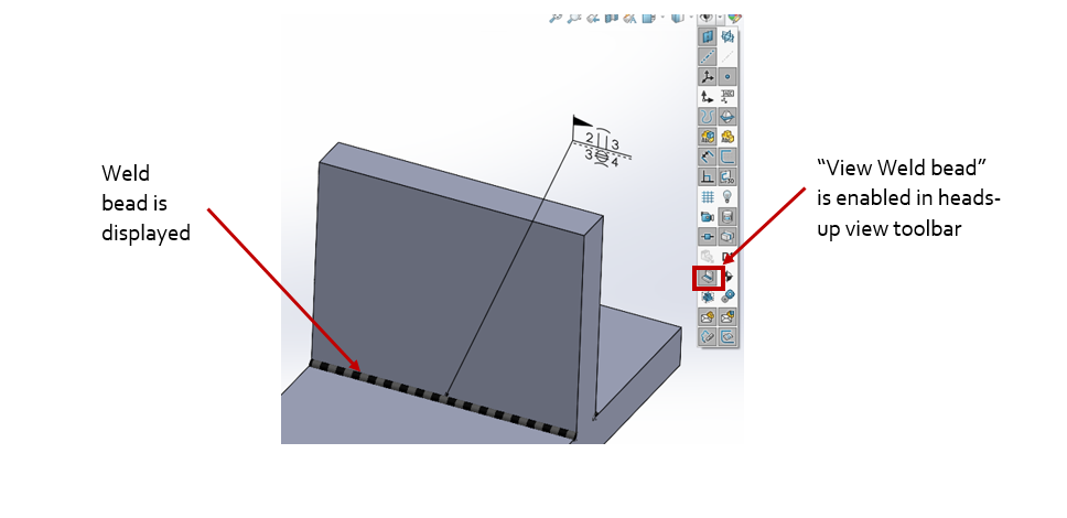
SOLIDWORKS Weldment Symbols are the annotations provided in the 3D CAD models and 2D engineering drawings for communicating the information about the location and the type of the welding to be done for a welded joint in a weldment structure/assembly. This piece of information is useful for the fabricator, supervisor, engineer, welder etc. who is working on the weldment project. Weld symbols usually includes an arrow depicting the location of the welding and the other symbols used provide the information about the type of welding to be done. In SOLIDWORKS, apart from specifying the weld symbol which specifies the type of weld etc., the actual location of welding to be done can be shown by the use of a weld bead. The below picture shows the use of a weld bead and weld symbol on a component.
Quite often during the modelling stage of the components the designers confront with the challenge of not viewing the weld symbols and/or weld beads even after their application in the components. This is because of the disablement of their display in few locations in SOLIDWORKS.
To enable viewing of Weld beads
In SOLIDWORKS, the Weld beads provide a convenient way of depicting the location and the length of the welding to be carried at a joint in a component.
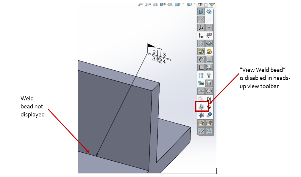
By default, the Weld beads visibility will be disabled due to the disablement of the “View Weld bead” option in the heads-up view tool bar as shown below.
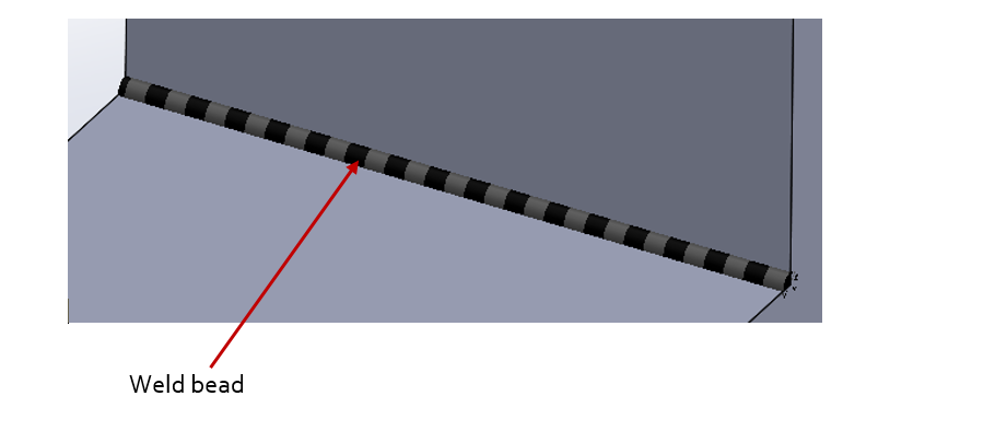
With the enablement of the above option, the display of the Weld beads is possible as shown below.
To enable viewing of SOLIDWORKS Weldment Symbols
In SOLIDWORKS, the Weld symbols provide a convenient way of depicting the type, location and other welding information for the welding to be carried at a joint in a component.
As the Weld bead is added, the weld symbol gets attached to it automatically. Double clicking on the weld symbol opens a Weld symbol editing dialogue box. The appropriate values for the weld can be set and can be saved as a style.
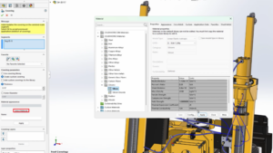
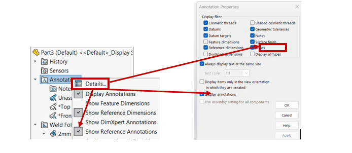
The viewing of the Weld symbol can be enabled by accessing the annotations properties by right-clicking on the annotations folder in the feature manager tree and clicking the Details option. In the annotations properties, by enabling the welds and Display annotations options and also enabling the show reference annotations options in the annotations contextual menu, will enable the viewing of the weld symbols in SOLIDWORKS 3D CAD model as shown below.
To summarize, the viewing of the “Weld bead” and “Weld symbols” in the SOLIDWORKS CAD model is important as it provides vital information for the engineer, welder, fabricator, architect etc. to accurately weld the parts at the required locations. By default, the Weld bead visibility will be disabled and can be enabled in the heads-up view toolbar. The Weld symbols can be enabled by enabling the options available in the annotations folder in the feature manager tree. During the modelling process, the designers can enable/disable the viewing of weld beads and/or weld symbols as necessary to display the same in their models and drawings.