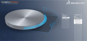
With the Advanced Hole tool, you can define advanced holes from the near and far side faces. Hole element fly outs help guide the process. A Favorites group box is available in the Property Manager.
Creating Advanced Hole Elements in SOLIDWORKS
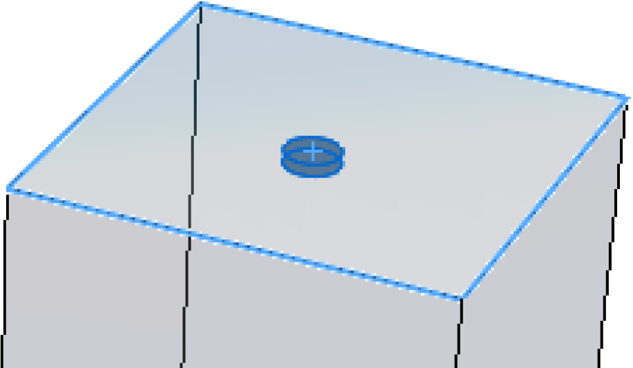
- Create a simple extruded block part.
To better visualize the previews, Ctrl +select all faces and click Appearances. In the Task Pane, under Glass, double-click clear glass to apply this appearance. - Click Advanced Hole
 (Features toolbar) or Insert > Features > Advanced Hole.
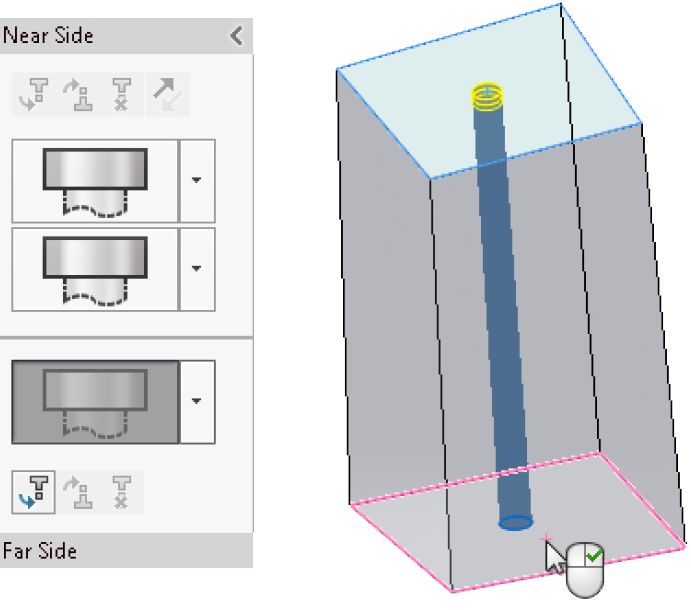
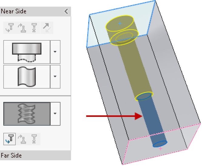
The Property Manager opens with the Near Side flyout displayed. - In the Property Manager, on the Type tab, under Near and Far Side Faces, select a face.
A temporary preview of the hole appears. The location is temporary, based on your initial selection on the face. You set the position later.
- Create a simple extruded block part.
- In the Near Side flyout, click Insert Element Below Active Element
 to add a Near Side element to the advanced hole.
 - In the Property Manager, under Near and Far Side Faces, select Far Side, then select the opposite face on the model.
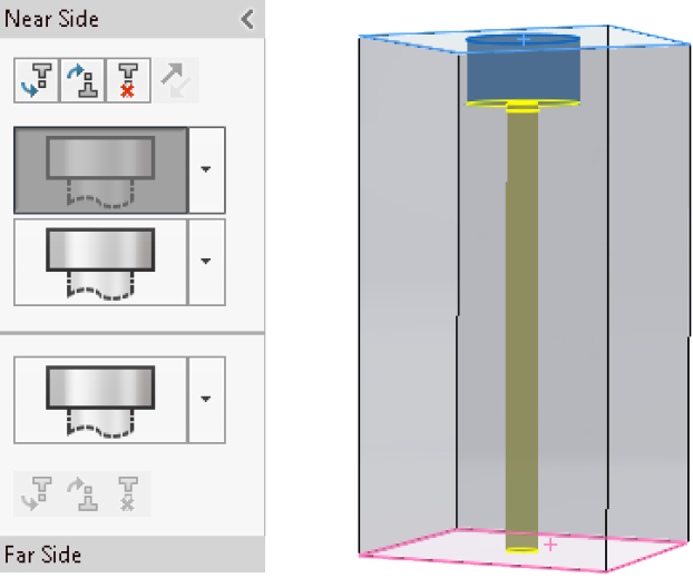
The Near Side fly out now displays two Near Side elements. The Far Side fly out is active and contains one element. A bar separates the fly outs.
The default element type in fly outs is Counterbore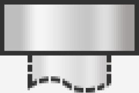 .
.
Next, you set the element specifications.
Setting Element Specifications
- In the Near Side fly out, select the top element to activate it. You want to keep Counterbore as the hole type but modify some settings.
- Under Element Specification:
- In Type, select Socket Head Cap Screw.
- In Size, select 1/4.
The temporary preview of the Near Side element is updated.
- In the flyout, click
 for the second Near Side element, then click Straight
  . You want to modify the specifications for this element.
 - Under Element Specification:
- In Type, select Screw Clearances.
- In Size, select 1/4.
- For Custom sizing, set End Condition to Blind and Depth
 to 1.
to 1.
The preview updates to show the modified size and depth for the Straight element.
In the flyouts, you can drag elements to reposition them. If the drag operation causes a failed element, that element is highlighted. Hover over the element to display an error message.
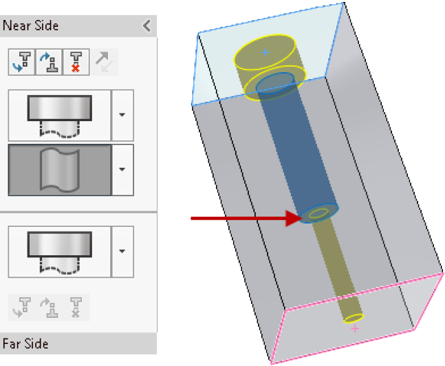
The Far Side element is set as Counterbore. You want to modify it to be a tapped thread element. - In the Far Side flyout, click for the Far Side element, then click Thread
 .
. - Under Element Specification:
- In Type, select Tapped hole.
- In Size, select 1/4-20.
The Far Side element updates up to the middle Near Side element because of the Up to Next Element end condition.
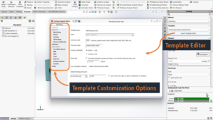
You can save advanced hole features as Favorites to reuse them. In the PropertyManager, on the Type tab, under Favorite, you can add, update, delete, save, or load a favorite advanced hole.
Next you create and position instances.
Creating and Positioning Advanced Hole Instances
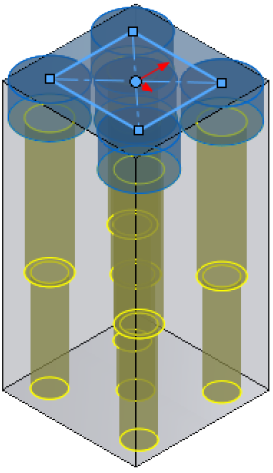
- In the PropertyManager, select the Positions tab.
You can select multiple points or use a sketch to create multiple holes.
If you forget to select the Positions tab and click , the software prompts you to select a point on the face to locate the hole. Click OK in the prompt to open the Positions tab and the Sketch toolbar.
 - Click Center Rectangle
 (Sketch toolbar) and sketch a rectangle, using the sketch origin
  on the face as the center.
 - Click to close the Center Rectangle PropertyManager and return to the HolePosition PropertyManager.
The software creates five instances of the hole, including a sketch point at the selected origin. You want to remove the center instance.
- Under Instances to Skip, select the center instance or to remove only this instance from the preview.
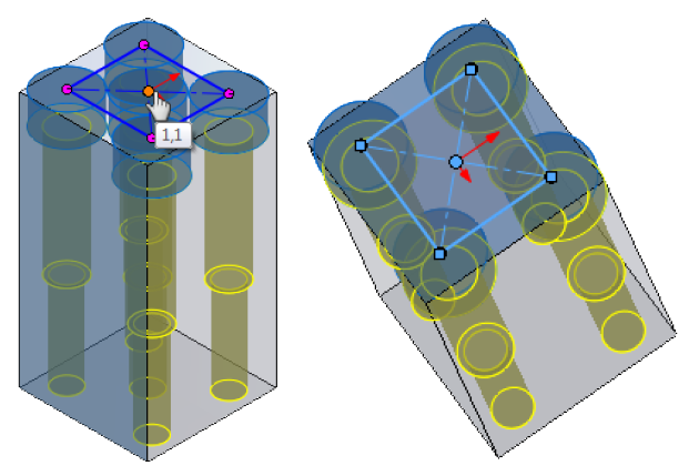
Under Sketch Options, you can select Create instances on construction geometry to create instances using construction geometry.
Find more updation in the 24th release of SOLIDWORKS. Attend Live SolidWorks 2017 Launch, Bangalore.