Insert Sheet Metal Bend Notes within SOLIDWORKS Model Based Definition
SOLIDWORKS Model Based Definition i.e., MBD also known as “Digital Product Information” uses the 3D Models to define the Product Manufacturing information, Geometric dimensions & tolerances to individual components and assembly.
The Most important advantage of using MBD, it reduces the ambiguity of referring 2D drawings for manufacturing process, reduce lead time for drawing reading and errors in manufacturing.
Following are the sequential steps involved in deriving the bend tables for sheet metal using MBD.
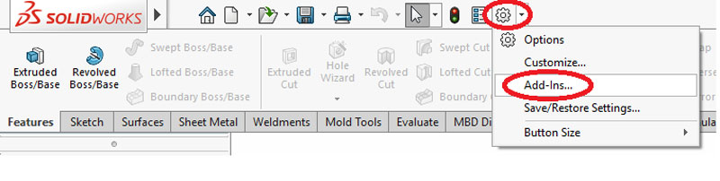
- To Start Model Based definition
- Go to menu bar >> choose options
- Select Add-ins
- Check in SOLIDWORKS MBD
- To Start Model Based definition
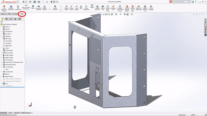
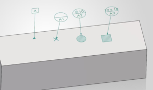
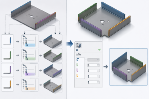
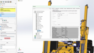
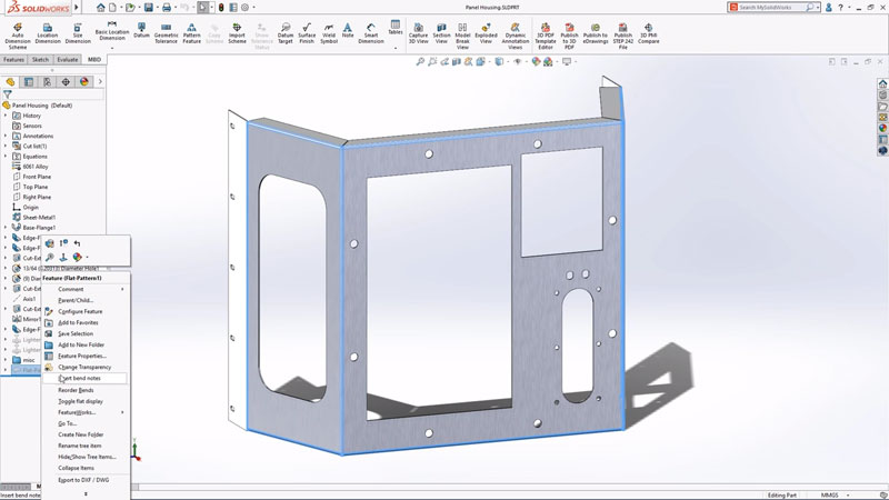
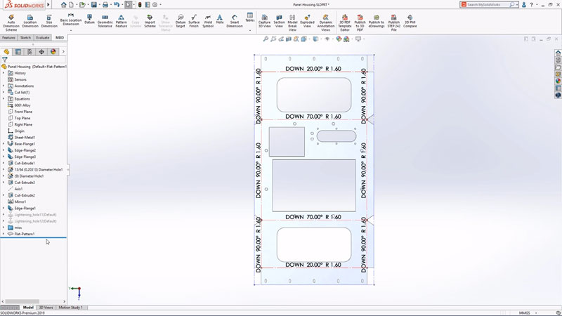
2. Inserting bend notes and flat pattern
- Go to Feature Manager design tree
- Right click on flat pattern option
- Select “Insert Bend Notes”
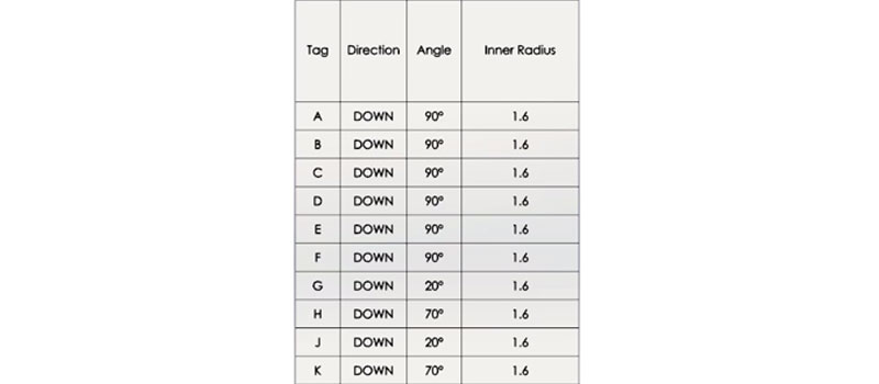
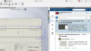
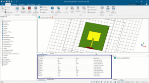
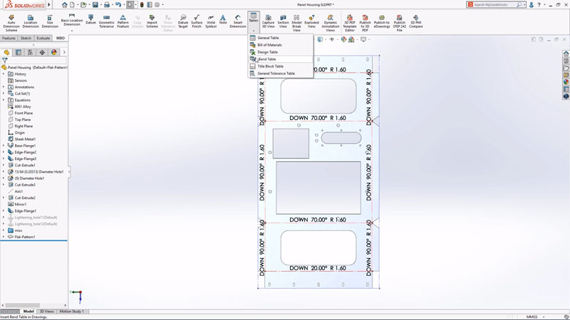
3. Inserting Bend Table
- Go to Command Manager
- Choose Tables
- Select “Bend Tables”, apply necessary annotations as per requirements and press OK
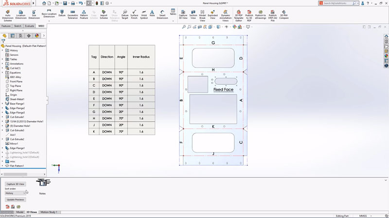
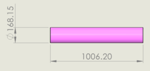
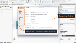
A Typical Bend Table used for Sheet Metal Fabrication