Specifying Tolerances for Hole Wizard in SOLIDWORKS
SOLIDWORKS 2019 has a capability for setting values for tolerance and precision when creating Hole Wizard features.
The Type tab in the Hole Wizard Property Manager includes Tolerance/Precision. Depending on the hole type the property manager displays options for tolerances that apply to the hole specifications.
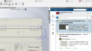
This section is also available for Hole wizard features in assemblies. Tolerance values automatically propagate to hole callouts in drawings. If you change values in the hole callout, the values update in the part. You can also vary tolerance values for configurations. Previously, you could only add parameters for tolerance and precision to Hole wizard holes by manually modifying hole callouts in drawings.
Following are the sequential steps involved to specify tolerances for Hole Wizard holes in SOLIDWORKS.
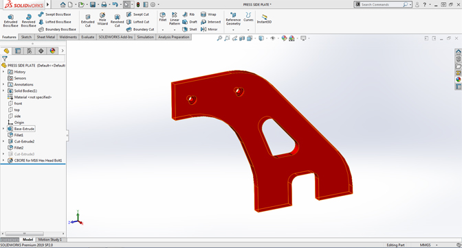
01. Open an existing part file
- ✔ Go to file menu >> click open
- ✔ Select the part file.
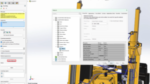
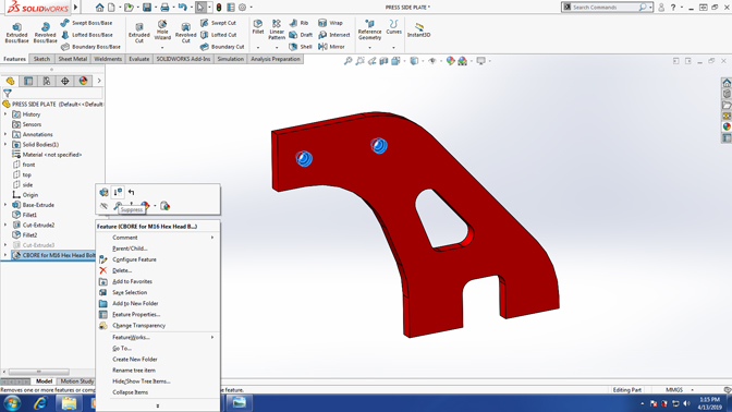
02. In the Feature manager design tree, right-click CBORE and click Edit Feature.
03. In the Property Manager, on the Type tab, Expand Tolerance/Precision
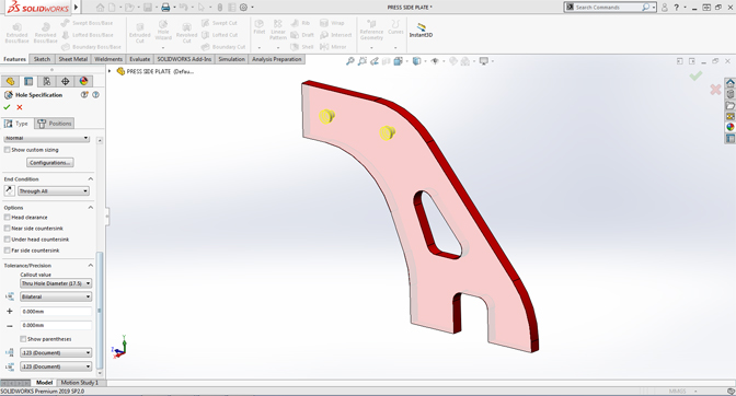
04. Under Tolerance/Precision, in Callout Value
Select Thru Hole Diameter.
- a) For Tolerance Type, select Bilateral.
- b) For Maximum Variation, Enter value.
- c) For Minimum Variation, Enter value.

05. Under Tolerance/Precision, in Callout Value
Select Counter bore diameter.
- a) For Tolerance Type, select Symmetric.
- b) For Maximum Variation, Enter value.
- c) For Unit Precision, select .12.