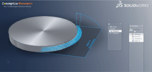
Pipe and Instrumentation Diagram of SOLIDWORKS
Every day we face great challenges of documentation corresponding to the industrial construction processes, where the use of pipes or installations with pressure equipment such as boilers, exchangers, material transport system by pipeline, etc. are involved.
If at any given time we require a modification to our system or maintenance of any kind, it is necessary to generate an identification drawing of the components of the system in addition to the reasoning of the operation of the system. For this, there is a system or diagram called Diagram of Pipes and Instrumentation (DTI) or better known as Piping and Instrumentation Diagram / Drawing (P & ID).
P & ID of SOLIDWORKS Electrical
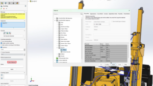
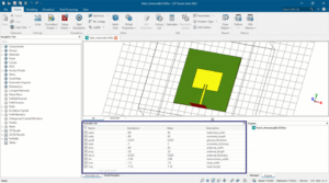
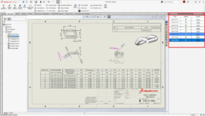
This Pipe and Instrumentation Diagram of SOLIDWORKS shows us in a simple way how our installation is constituted because many times the installation is very large and physically it is very difficult to understand how it works or how its components are distributed.
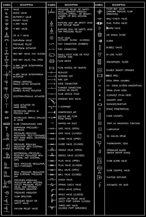
In this type of diagram we can see a series of symbols that will allow us to identify the components of the system; such as: valves, pumps, pipes, dimensions controls, sensors, gaskets, etc.
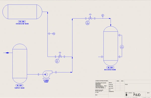
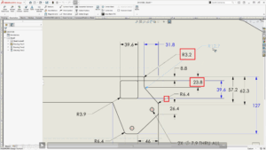
As you can see in the image, we can see annotations that simplify the understanding of it. In the case of symbols, they have a standard under a standard that allows us to be in the same standardization so that anyone who sees this plane can understand it; in the same way, a table with all the symbology used can be attached.
In SOLIDWORKS we can carry out the development of this type of diagrams. For this we only have to help us from the drawing platform. It will be as easy as taking an element, dragging it to our system and then joining it by means of lines in different layer formats.
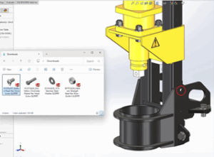
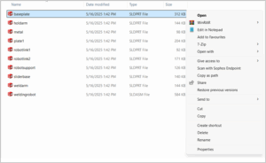
Thanks to the interaction that SOLIDWORKS has, we can make our own 2D block libraries. This library will be completely personalized. We can generate our own symbols, upload the existing symbols or also download a file with the general symbiology we are going to work with.
With this we can comply with the regulations of our P & ID by working in a simple, fast and innovative way, sharing the information and fostering the integration between the engineering and construction departments.