

In today’s competitive world, manufacturing highly accurate & precise components at low cost is a big challenge. To accomplish this, designers use the language of Geometric Dimensioning & Tolerancing (GD&T) required to accurately manufacture the parts. While specifying the Product Manufacturing Information (PMI) in their documents, designers make use of datums to specify the references on flat faces or planes applicable for machined components in general. However, when the component is made up of uneven, rough, curved or bulged surfaces such as plastic components, forged components, cast components etc., specifying the datums is difficult as there will be no flat faces. Under such circumstances, the datums are specified using datum targets on the uneven or curved surfaces by selecting a small portion such as points, edges or areas depending on the geometry of the component.
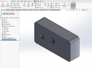
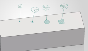
In SolidWorks Model Based Definition (MBD), the datum targets can be easily added to the parts using the datum target feature. The datum targets are added onto the component surfaces as points and areas as shown below.

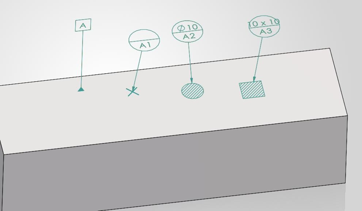
To add a datum target in SolidWorks MBD, a datum must be first created and can be added in different ways. On a curved/uneven surface, the datum can be created by first creating a plane at the highest point (for a convex surface) or by selecting 3 points (for a concave surface). After creating a plane, the datum is added. Further, the datum targets can be placed on the required point, edge, on the plane.
Datum Target at a Point or Vertex
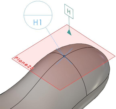
In the image shown below, for a plastic part having curved surface, Datum target as a point will be placed at the intersection of 2 edges. H is the datum placed on a plane created at a highest point on a bulged portion. H1 is the datum target point referencing the datum H. Point H1 represents a point on which the plastic part will be placed on the inspection table.
Datum Target on an Edge
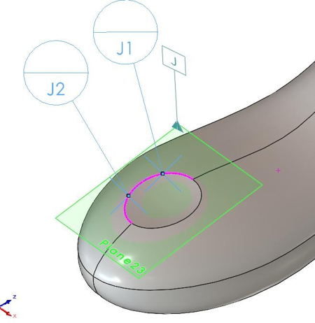
J1 and J2 are the datum targets added to the edge of the plastic part and J is the datum placed on a plane.
Datum Target on the face
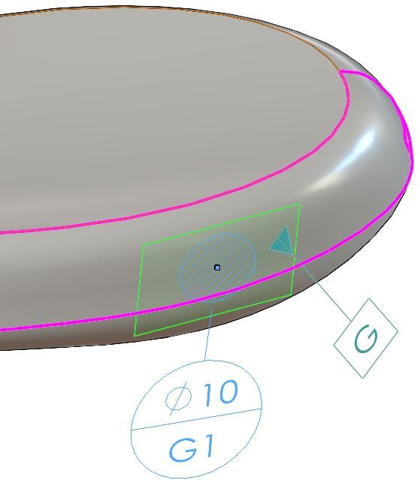
The image below shows the datum target in the form of a circular area provided on a curved surface of a plastic part. The datum target G1 is defined by a circle of ø10mm. The reference for placing the datum target is G
Conclusion:
Datum targets serve as references like datums. While datums serve as references on components with flat surfaces such as machined components, datum targets are especially used on components that do not possess flat surfaces/even surfaces. These can be cast components, plastic components, forged components etc. For adding the datum targets, particular points, edges or areas on the part are chosen such that, the part can be rested on such entities and is stable in that position without any play. It should be noted that for better stability of the component, three datum targets at different positions to be provided.