One of the main advantage of Simulation in SolidWorks is the possibility to validate the assemblies. Finite element analysis of an assembly provides us insight into the behavior of individual components and the load transfer taking place through components. Whenever we have assemblies, setting up contact definition will be very important.
Representation of Contact Sets in SOLIDWORKS Simulation
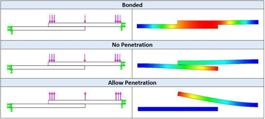
Using contacts in structural problems, it’s possible to define the way parts are connected to each other and interact with each other during the analysis. The following three options are available: 1) Bonded 2) No- Penetration 3) Allow Penetration
Representation of Contact Sets
- Bonded: Using this option as contact conditions, the connected parts act as welded. Two parts will be acting as one single part. The bonding of parts ensures continuity of the model to transfer forces or loads, between bonded components. Slightly interfering parts can also be bonded. For bonding contact to take place, the components should be touching or be within a small distance from each other.
Bonded Contact before and after loading
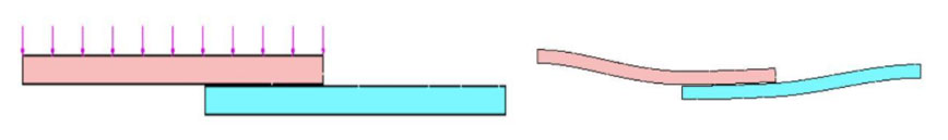
- No-Penetration Contact: This type of contacts prevents interference between two components. The components are free to move depending on the load applied or displacement given, but the selected parts or faces do not penetrate each other during the simulation. By default, bodies do not penetrate themselves if the deformation during simulation is sufficient to cause self-intersection. The global contact can be defined as bonded and locally its possible to define no penetration for components of interest based on their interaction during the initial setup of an assembly or during the analysis. Surface to surface contact formulation is applied for no Penetration contact. In Nonlinear studies, no penetration should be applied using component set.
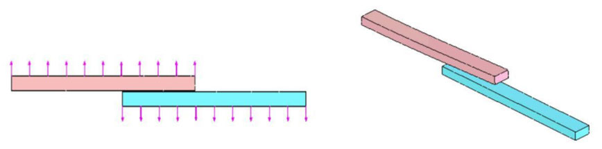
No Penetration contact before and after loading
- Allow Penetration: Selected parts or components or bodies can penetrate each other during simulation. The program treats source and target faces as disjointed. This option should be used, only when, we are sure that loads do not cause interference during the simulation. Making use of this option generally saves time. Do not use this option unless you are sure that loads will not cause interference of the components. The Allow Penetration option overrides existing component contacts.