Creating terminal strip documentation is an error prone and tedious process. Creating terminal strip drawings, cabinet layout and industry standard charts that illustrate how the terminal strip is assembled and how the wiring is to be connected must be done to fully document a control panel. Luckily, SOLIDWORKS Electrical has fantastic tools that take this process down from hours to minutes while at the same time reducing error.
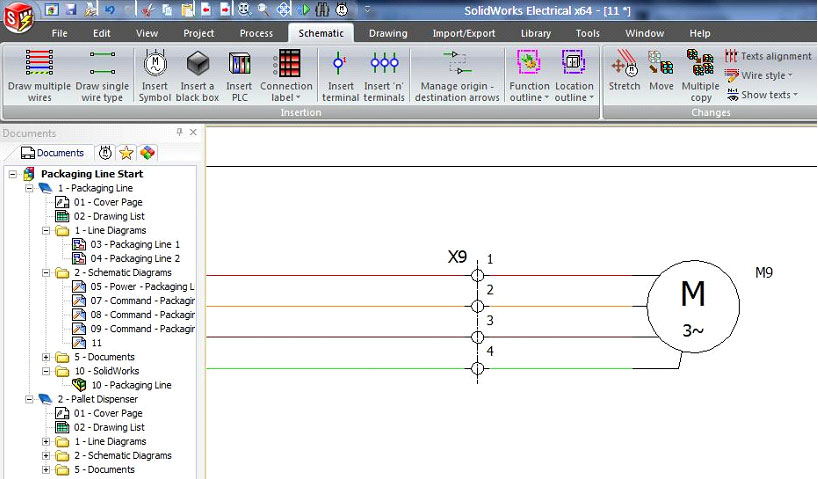
SOLIDWORKS Electrical has a complete terminal strip management system, from the insertion of terminals in drawings, to the automatic generation of the terminal strip drawings, to cabling the terminals. First of all, as you design your schematics with SOLIDWORKS Electrical, the connections to terminal strips are automatically captured using the “Insert “n” Terminals” option. The designer simply drawings a line across the multi-wire circuit seen below and terminal numbers that are associated with a terminal strip appear, in this case terminal strip mark “X9” is created with terminal numbers 1 through 4.
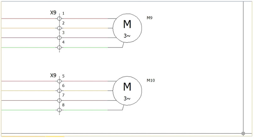
Terminal numbers can be reassigned if need be. Another cool fact is that if more terminals on the same strip are added, the terminal numbers are continued, for example 5-8 as seem below.
The terminal strip contains all the connection information between the components and wires/cables they are connected to and are managed using tools built into SOLIDWORKS Electrical. As you can see below, some of the connections are indeed cables, as they are grouped together in cable numbers, like W6, W7, etc.…
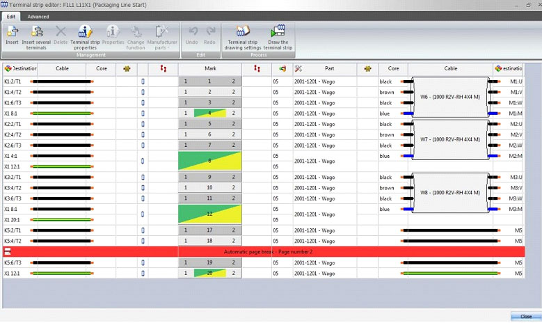
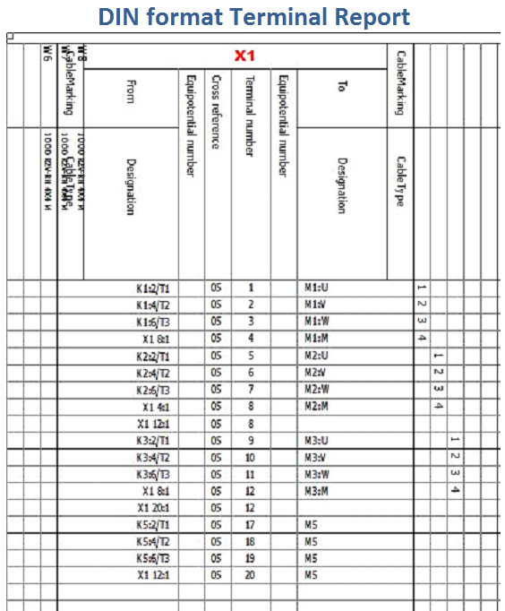
From this detailed terminal strip information panel, drawings and connection reports in drawings formats or tables can be created. These tables are in the in the DIN format as seem below. SOLIDWORKS Electrical supports the Horizontal and Vertical DIN formats out of the box.
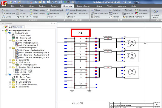
For a more illustrative way of documenting the terminal strip you can use the terminal strip drawing format as shown below. This is a simplified drawing showing the terminal strip “X1” with 18 blocks on the terminal and the wires and cables connected to the strip, plus where the wires and cables are going, in this case to the motors “M1” through “M3” SOLIDWORKS Electrical created this drawing automatically from the schematic!
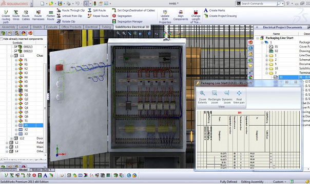
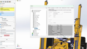
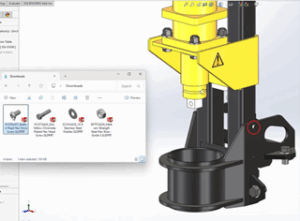
Finally, is there a better way of illustrating the terminal strip and wiring than in pure 3D. SOLIDWORKS Electrical 3D, which connects the schematic in 2D to the assembly in 3D, allows for the layout of the control panel with terminal block and the automatic wiring from the schematic definition. Layout of the control box is as simple as dragging and dropping the components called out for by the Electrical schematic and then hitting the “Route Wires” or “Route Cables” button in the software. The wire lengths are auto-calculated and are sent to the terminal strip drawing documentation in SOLIDWORKS Electrical 2D schematic software as well. Note how the 3D user has full access to the schematic and DIN style reports inside SOLIDWORKS itself.