Most of the time there is ambiguity in deciding whether to consider node values or element values for stress in the results and mesh refinement is sufficient or not. Let us look at how node values and element values makes a difference in our final stress result values.
Node Value Vs Element Value in SOLIDWORKS Simulation
The stress values are calculated first at certain locations called as called Gauss or quadrature points which are located within each element. Finite element analysis calculates stresses at the nodes of each element by extrapolating the results available at the Gauss points [Figure 1]. By default, in Solidworks simulation node values are shown. This can be changed to element values in simulation options.
After the analysis is finished i.e. simulation is run, at each node of every element, nodal stress values are obtained.
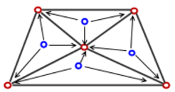
Figure 1: Representation of Gauss points within an element
In Figure 1, the element nodes are represented by red dots whereas Gauss points are represented by blue dots
First order tetrahedral elements i.e. draft quality has one gauss point in their volume, whereas second order tetrahedral elements have four Gauss points. A node will be common for several elements. Each element gives stress results that are slightly different from neighboring element[Figure 2]. For example, if a node is common to three elements, there can be three slightly different values for every stress component at that node.
When nodal stress values are plotted, the software averages the stress values from all adjacent elements contributing to the stresses at that node [Figure 3]
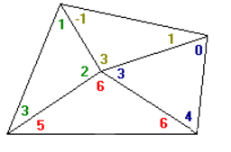
Figure 2: Stress values extrapolated from Gauss points to nodes of each element
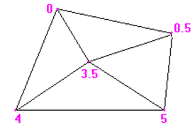
Figure 3: Nodal stress values averaged at each node.
The other option is to plot element values. The program gives single element stress values as mean value from all gauss points present within each element [Figure 4]. Although these stresses are averaged between Gauss points, they are called non-averaged stresses (or element stresses) because the averaging is done internally within the same element only.
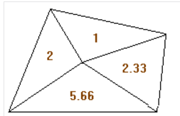
Figure 4: Element stress values averaged within the element
There will always be difference between node values and element values, but a large difference indicates that meshing is not refined sufficiently at that location. Therefore, run the simulation after refining the mesh at that location and check for difference between node and element values for accurate results.