The SOLIDWORKS Section View is a great tool to investigate the details of complicated parts and assemblies. For instance you can use the section view when:
- A Shell command is used with or without multi-thickness checked,
- A Hole wizard is used to make sure holes are aligned,
- Assembling many parts and you need to make sure they don’t collide,
- You need to examine the motion of a mechanism.
Considering the fact that SOLIDWORKS models are often complicated in design and orientation, Customized SOLIDWORKS Section Views can be very useful to cut the model in a specific orientation and depth. To make a customized section view a custom plane is required. Therefore, a reference plane must be defined to be utilized with your section view. Custom reference planes are defined based on principal planes, or other predefined planes, or faces on the model.
However, defining a reference plane takes a bit of time and sometimes has limits. What if we could rotate the model to a desired orientation and then cut the model right at the view orientation. This is solved in recent SOLIDWORKS versions. A reference plane could be created parallel to the screen without using the Plane PropertyManager. In SOLIDWORKS 2015, a point had to be defined and used to create the reference plane.
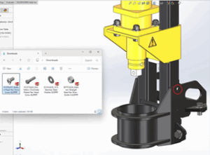
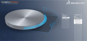
But for SOLIDWORKS 2016, you only need to select a face, then right-click on it, and select “Create Plane Parallel to Screen” from the shortcut menu. The following image demonstrates the process:
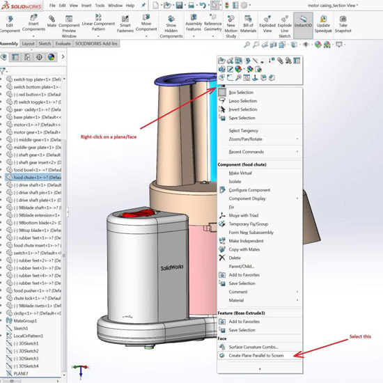
Create Plane Normal to Screen
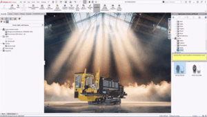
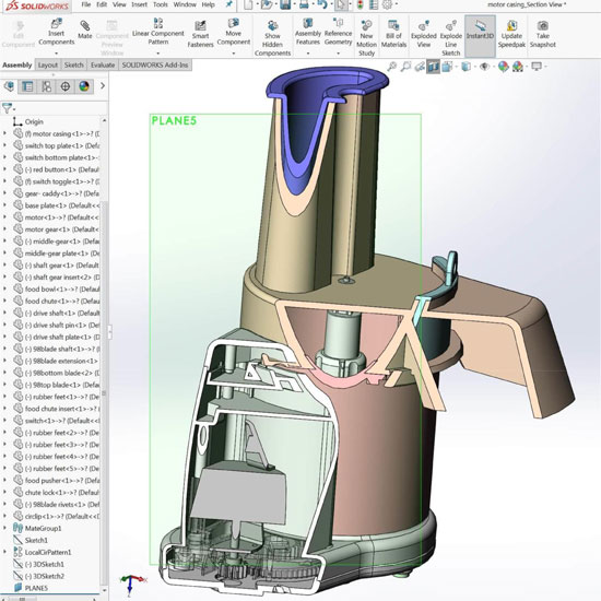
SOLIDWORKS Parallel to Screen Section View
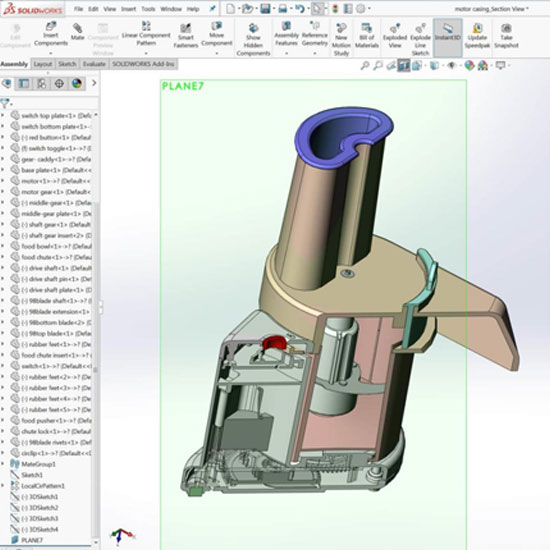
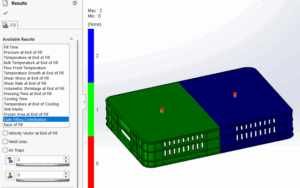
The following image represents a section view and the reference place which were used to make that section view. The assembly model has been rotated into a specific orientation and the parallel to screen reference plane was used to create the section view. Depending on the orientation and the selected face for reference plane, the section view would have the components cut.
Customized Section View
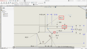
Adjust the Section View
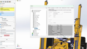
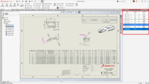
When you edit a Section View, you have various options for changing the depth of the view and also rotating the cutting plane up or down and side to side. The following image demonstrates the editing abilities. The yellow arrows are what are used to manually adjust the orientation of the cutting plane and also the depth of the cut.
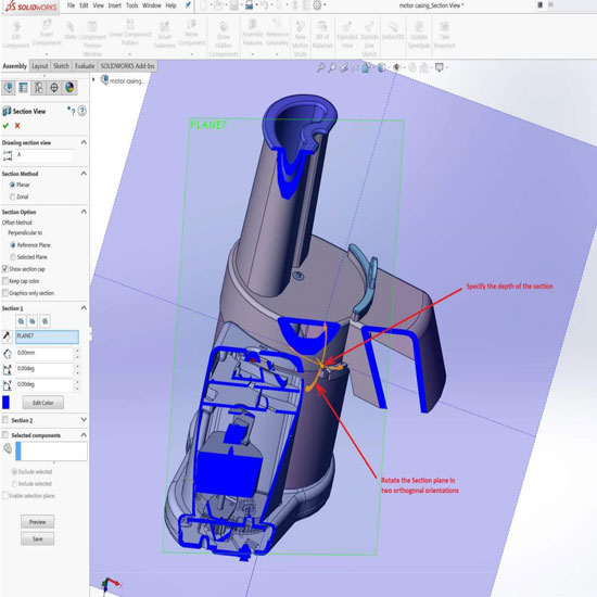
Edit Section View to Displace or Rotate the Section Plane