A Heat Pipe is a highly efficient thermal management device composed of a metal pipe made from materials with high thermal conductivity, such as copper, aluminum, or other similar metals. The interior of the heat pipe is sealed and contains a working fluid, which facilitates the heat transfer. Heat pipes are widely used in various consumer electronics, including desktops, laptops, and smartphones, to effectively transfer heat from high-temperature surfaces to cooler areas, ensuring optimal thermal performance and preventing overheating. The SOLIDWORKS Flow Simulation Electronic Module offers specialized thermal management tools designed to provide the most accurate thermal analysis for electronic PCB boards and enclosure designs. In this blog, we will explore the process of defining a heat pipe within the SOLIDWORKS Flow Simulation environment using the Electronic Module, ensuring precise thermal performance evaluations for electronic components and systems.
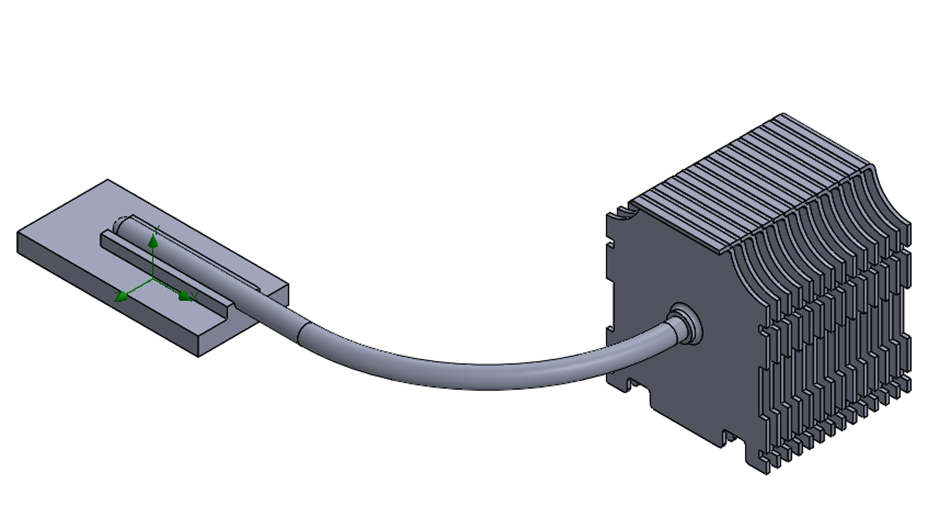
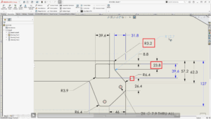
Fig1: Heat Pipe Contact details
How to define Heat Pipe in SOLIDWORKS Flow Simulation?
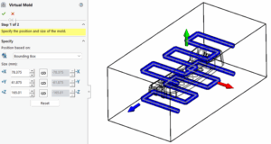
Step 1: Select Heat Pipe from the Simulation Setup Tree
Right-click on “Heat Pipe” & use “Insert Heat Pipe”

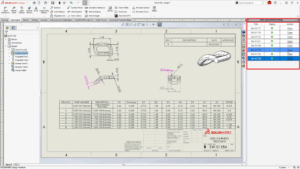
Fig2: Heat Pipe option in Flow Simulation Tree
Step 2:
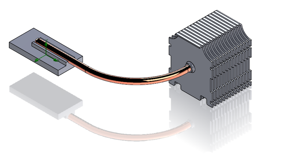
In the “Selection” area select the Heat Pipe component from Graphics Area or Feature Manager Tree.
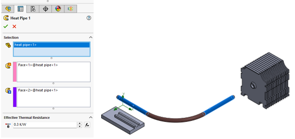
Fig3: Heat Pipe Definition
Choose the faces of the heat pipe for “Heat In Face” and “Heat Out Face” from the Heat Pipe Geometry as shown in Fig 3.
Set the Effective Thermal Resistance of the Heat Pipe and click on “Ok”.
With the above simple steps, we can define the “Heat Pipe” Boundary condition in SOLIDWORKS Flow Simulation.
Heat pipe geometry should not be hollow, that means indirectly simple solid geometry(ex.Solid Sweep) will represent Heat Pipe Virtually.
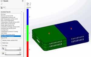
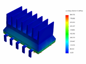
After Solving the setup we will get results as follows.
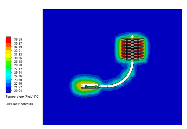
Fig4: Fluid Temperature Cut plot
This approach eliminates the necessity of modeling the complex two-phase physics within the device and Material definition from “Engineering database”. Heat Pipe definition one of the effective method for Consumer cooling modules, instead of Solid Material Definition.
Note: The Heat Pipe feature is available in the Flow Simulation Electronic Cooling Module.
Read Few More Blogs:
SOLIDWORKS Flow Simulation Solver Stuck at “Preparing Model”
Improved Geometry Handling in SOLIDWORKS Flow Simulation to Resolve Holes in the Mesh Error.
How to find Fluid Volume in SOLIDWORKS Flow Simulation?
Ensure Product Thermal Performance with SOLIDWORKS Flow Simulation Electronic Cooling