In today’s world of high-speed electronics, PCB plays an important role in ensuring reliable data transmission between the components. As the data rate increases, the PCB trace carrying those high-speed digital signals behaves like a transmission line and maintaining the signal integrity becomes more challenging. Even a small variation in the PCB design can lead to signal integrity issues such as reflections, crosstalk and signal degradation.
To address these challenges, electromagnetic simulation tools such as CST Studio Suite are used during the design phase of high-speed PCBs. It helps us to analyse the signal behaviour and measure the channel performance by identifying potential signal integrity issues.
In this blog, we will consider a high-speed Ethernet switch PCB to perform “Signal Integrity Double Data Rate (DDR) Analysis”. It focuses on evaluating signal quality through eye diagram analysis and identifying the major signal integrity issues.
Signal Integrity Analysis of an Ethernet Switch using CST Studio Suite:
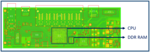
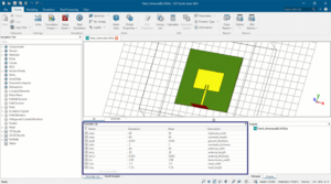
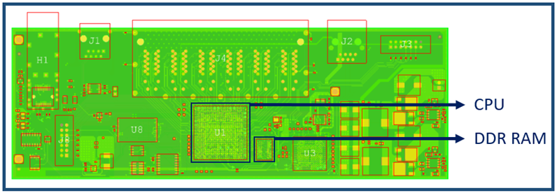
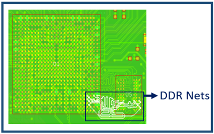
Signal Integrity (SI) is the ability of an electrical signal to propagate through a PCB without any distortion or loss of quality. Signal integrity analysis begins with importing PCB files into CST Studio Suite. We have imported a PCB file using the ODB++ format, which also supports PCB files from different software like Cadence Allegro, Hyperlynx and Zuken. Once the design is imported, it generates a detailed 3D model of the Printed Circuit Board (PCB) as shown in fig. 1. It includes all the physical elements such as copper traces, nets, vias and dielectric layers. Here, we are considering the DDR data nets DQ 0 – DQ 7, as they operate at very high data rates and they are highly sensitive to signal integrity issues. We consider these nets to analyse how signals propagate through the PCB routing paths.
Upon defining the high-speed nets, we perform signal integrity analysis using CST Studio Suite to observe the voltage across the signal path and evaluate its overall signal quality.
DDR Signal Integrity Results:
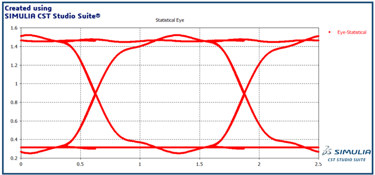
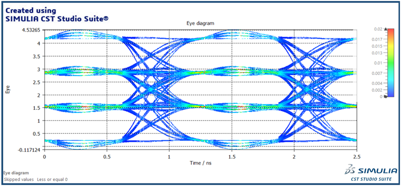
Signal Integrity of a DDR channel is evaluated using an eye diagram, which is one of the most effective techniques to analyse the channel performance. An eye diagram is generated by overlapping multiple bits of transmitted data into a single plot. It provides a clear visualization of signal quality at the receiver end and makes it easier to analyse the overall channel performance. An eye diagram helps in identifying signal integrity issues such as noise, jitter, reflections and Intersymbol interference (ISI). Vertical opening of the eye indicates the noise margin, showing how clearly the receiver can distinguish between logic “0” and logic “1”. In the same way, horizontal opening represents the timing margin, which reflects the timing variations and jitter.
In general, a wider and more open eye pattern indicates a better signal integrity, as shown in Fig. 2. It suggests that the channel has sufficient bandwidth to support high-speed transmission and the receiver can easily distinguish between different voltage levels. On the other hand, a partially closed or distorted eye makes it difficult for the receiver to identify the correct data bits, which leads to signal degradation.
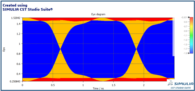
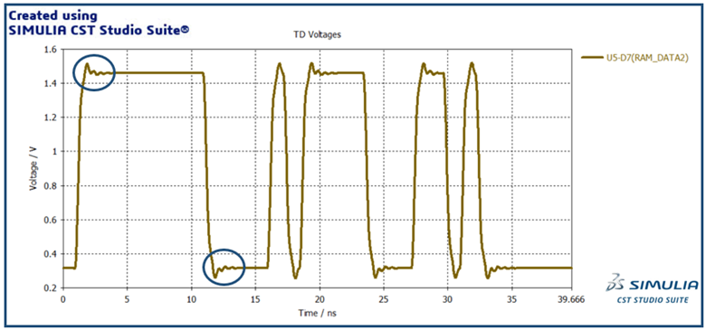
Overshoots and Undershoots are transient voltage variations where the signal exceeds its intended maximum voltage level or drops below its minimum level, as shown in Fig. 3. It is mainly due to impedance mismatch along the transmission path or rapid signal transitions that cause signal distortion.
Intersymbol Interference (ISI) occurs when the signal corresponding to one bit interferes with another bit of the same signal. It makes it difficult for the receiver to correctly interpret the transmitted data, which leads to bit errors. It is mainly due to the channel losses or limited bandwidth along the PCB traces.
“CST Studio Suite provides a powerful platform to analyse signal integrity in high-speed PCBs. It allows designers to simulate signal behaviour and visualize results using eye diagrams. It helps in identifying issues such as reflection, crosstalk, and noise at an early stage of PCB design.”
Explore the capabilities of CST Studio Suite to enhance your signal integrity analysis and unlock the full potential of your high-speed designs.
Author Details:

Technical Support Associate – CST Studio Suite (Electromagnetic Simulation)
“As a Technical Support Associate for CST Studio Suite – Electromagnetic Simulation, Likith R focuses on providing technical support and training to customers. He assists in troubleshooting software-related issues, optimizing simulation workflows, and enabling customers to achieve accurate results through a simulation-driven approach, to reduce their product development time.”