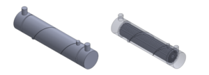
Calculating the fluid region in Computational Fluid Dynamics analysis is an important step in understanding and optimizing fluid flow behaviors in a system. The area of a system where fluid (gas or liquid) is present is called the fluid zone.
Purpose of Fluid Volume Extraction:
- To maintain the design optimal fluid flow path to reach our goals.
- To forecast the fluid movement, surface interactions, and the effects of various variables (such as temperature, pressure and turbulence) on the flow.
- To identify how velocity, pressure, and other flow parameters are distributed within the fluid region, enabling more accurate optimization of the system design.
- Calculating the fluid region will make it easier to determine where the flow may split or recirculate, which could impact system performance.
- To understand how fluids transmit heat, by precisely modeling the fluid region, heat transfer rates can be optimized in engines, heat exchangers, and electronic cooling systems, guaranteeing that the system stays within ideal temperature ranges.
How to extract Fluid Volume in SOLIDWORKS Flow Simulation:
SOLIDWORKS Flow Simulation has a wide variety of Preprocessing features, which gives flexibility in CFD Analysis Setup & ensure fluid tracking. “Check Geometry” is one of the most useful & underrated features available in SOLIDWORKS Flow Simulation, which allows us to verify solid and fluid bodies.
As mentioned above, extracting fluid regions during the setup process gives ideas about fluid flow patterns. Usually, we use “Check Geometry” command for checking whether geometry fully sealed for internal analysis.
Let us see how to use the SOLIDWORKS Flow Simulation “Check Geometry” feature to obtain fluid Volume with easy-to-follow instructions for the following pump assembly, which includes the hollow body, bladed impeller, inlet lid, and outlet lid.

Fig1: Model Geometry
Steps:
1. Click on “Check Geometry” command available in Command Manager >Flow Simulation Tab
2. In the “State” window, we can use check boxes to include or exclude components from the flow Simulation Setup.

Fig 2. Check Geometry
3.Enable the “Create fluid body assembly” check box and use the “Check” button. SOLIDWORKS creates a Fluid boundary part document automatically in the background.
4. Immediately, you will get a bottom window, which shows “Check Geometry” results. Results contain the following information:
- Geometry suitable for Internal or External analysis
- Fluid Volume with units
- Solid volume with units

Fig3. Check Geometry Results
Note: Sometimes, we will receive the status “FAILED” since the model does not have any closed internal volume (i.e. Non Watertight Model).
5. Close the “Check Geometry” Status window and switch the model by using the “Window” option in the Title bar or with a Keyboard short cut “Ctrl+Tab”.
We will get Fluid Volume from the previous setup (Pump).

Fig 4. Fluid Volume

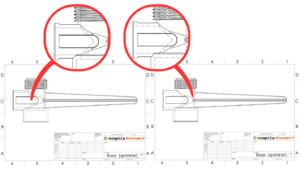
Fig5. Actual Geometry Section View

Fig6. Extracted Fluid Volume Section View
By extracting fluid regions, we can ensure precise flow behavior, fluid-structure interactions & patterns. We can reduce Energy losses and improves heat transfer performance of Complex fluid dynamics.
If you wish to know advanced features in SOLIDWORKS Flow Simulation or have an in-person session, do reach out to us through [email protected] or Request a DEMO.


