In every industry, the production cycle time for components/products is critical since it directly affects the production efficiency and cost involved. Less cycle time in turn reduces the cost involved per part and increases productivity. Since the plastic components, which we use in day-to-day life is been produced by various industries, even a small reduction in cycle time may lead to massive cost saving and higher output rates. In plastic injection molding industry, cycle time involves the time required for four key phases – injection, cooling, ejection and mold reset.
In this blog, we will focus on how to optimize the cycle time during the cooling phase using SOLIDWORKS Plastics. Cooling phase is the longest and most critical part in this cycle, which often account for 50 to 80 percent of the cycle time.
Factors affecting Cycle Time during Cooling Phase of Plastic Injection Molding:
- Low thermal conductivity of mold material likely steel molds leads to longer cooling times.
- Thicker mold walls retain heat longer, increasing cooling time
- Improper cooling system design slows the cooling time
- Higher injection pressure & extended packing pressure generate and retain heat longer
How SOLIDWORKS Plastics enables us to optimize cooling phase In Injection Molding
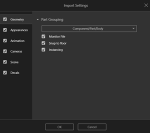
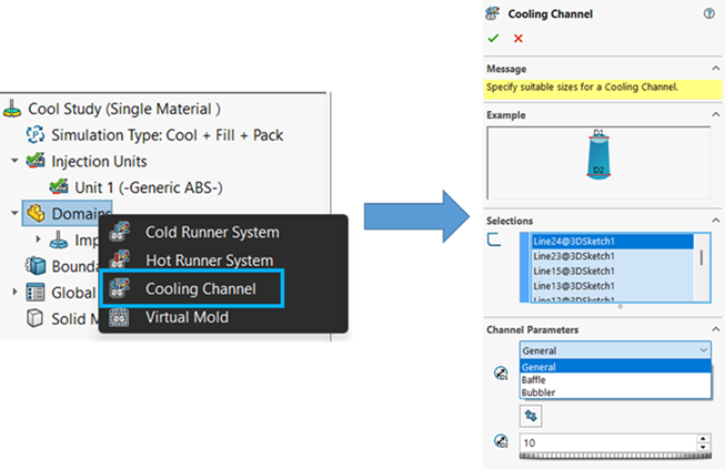
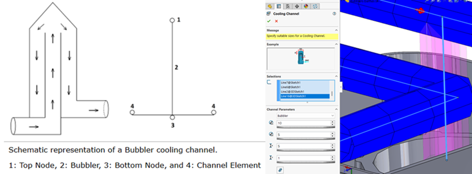
In SOLIDWORKS Plastics Premium, we can analyse not only the fill and pack stages but cooling of the mold cavity too. In Cooling analysis module, we can specify the cooling channels with parameters such as coolant type, flow rate & channel design and use virtual mold to analyse the cool stage. We can assign the existing 2D sketch entity in model as cooling channel. Under the domains, we can specify the cooling channel and size. Advanced runner channel types like baffle/bubbler can be assigned when there is a limited area available for cooling channels.
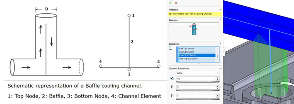
Baffle type of cooling channel are used in molds to create a turbulent flow by forcing the coolant to change direction as it moves through the system. Thereby enhancing the heat transfer efficiency by increasing the contact between coolant & hot mold surfaces. We can specify a baffle channel using a T- shaped sketch geometry with three different sketch lines.
While bubbler type of cooling channel is similar to baffle, but it actually comprises of two differently sized diameter channels i.e. one inside the other. The coolant will be pumped up through the inner channel and then spayed onto the outer channel.
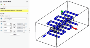
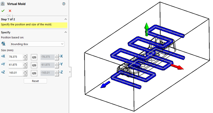
We can create a virtual mold and assign material based on custom size or bounding box of the mold cavity & runner systems.
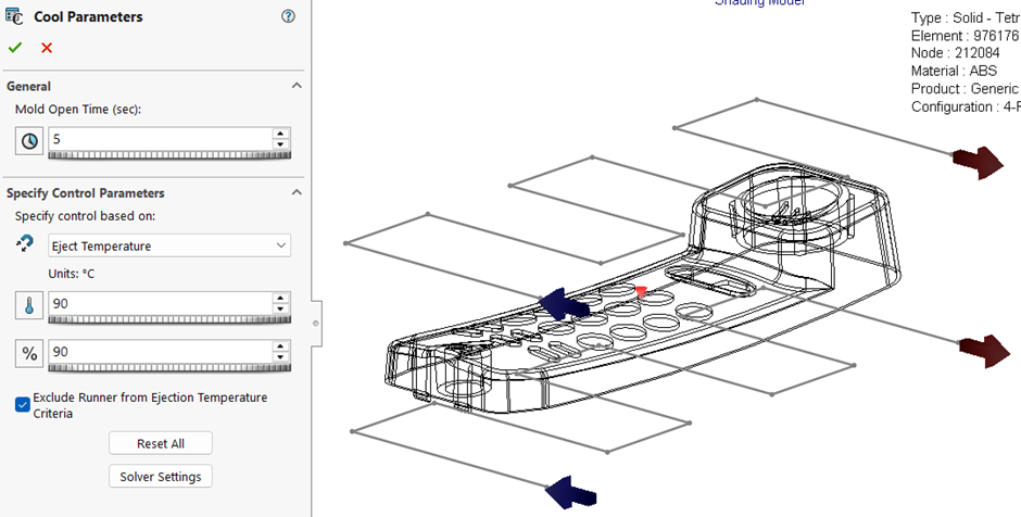
In addition to the above, we can specify the parameters such as mold open time which is equivalent to the overall cycle time (fill time + pressure holding time + cooling time + mold open time). We have option to mention the eject temperature or cooling time (which the solver uses the input to calculate the temperature reduction of polymer inside mold cavity) to specify end limit for cool analysis.
Once we run the cool analysis study by setting up the coolant channels & virtual mold, we can validate the setup by;
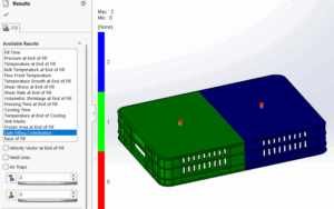
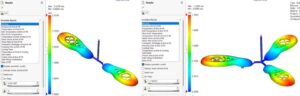
- Checking if the cooling had occurred across the mold evenly or not through the cooling time distribution plot. If presence of hot spot or longer cooling time areas is predicted, we can understand the inefficiency in cooling.
- If large pressure drop is observed in the pressure plot of coolant system, we can understand that there is problem in cooling channel.
Till this, we have seen how we can setup the cooling analysis in SOLIDWORKS Plastics Simulation for a mold cavity and analyse the cooling channel design. To know more about the capabilities, please do reach out to us at [email protected]
Author Details:

Ramesh Aravind is a Customer Success Associate based out of Chennai, Tamil Nadu. He has completed Master’s in Engineering with specialization in Industrial Metallurgy. He had joined Conceptia Konnect team in August, 2022 and has a good experience in SOLIDWORKS, Simulation & 3DEXPERIENCE Works solutions.