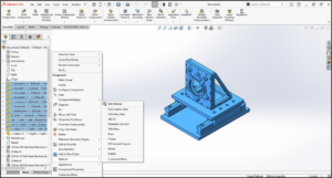
Mate Reference feature can be added to frequently used components to automate common mates. When inserting a component with a mate reference, either drop it onto appropriate mating geometry or onto an existing assembly component with a mate reference of the same name. This feature allows to realize the benefits of Smart Mates without the requirement of having the part open. By identifying a face, edge or vertex in the part as the mate reference, Smart Mates can be initiated while dragging and dropping the part from Windows Explorer or the Task Pane.
Mate References allow for up to three different specified entities. There are 2 ways to utilize them.
- Default mate references, which uses the Primary, Secondary, and Tertiary references within the feature as priorities.
- To create a named mate reference. This technique is for frequently used components
Adding Mate Reference
Let’s use mate reference for a Gear Shaft assembly. First create a gear with a D-hole and a stepped shaft in a part template.
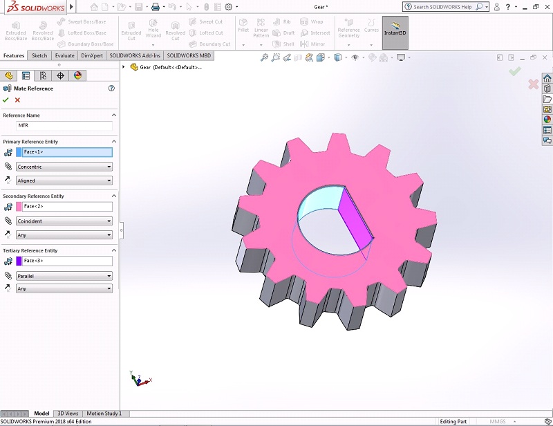
- Open the created part Gear. Click “Mate Reference”. Under Reference name type MTR. Under Primary Reference Entity select the cylindrical face of hole, type of mate as Concentric and select Aligned for orientation of the mate created. Under Secondary Reference Entity select the face of gear, type of mate as Coincident and select Any for orientation of the mate created. Under Tertiary Reference Entity select the planar face of hole, type of mate as Parallel and select Any for orientation of the mate created.
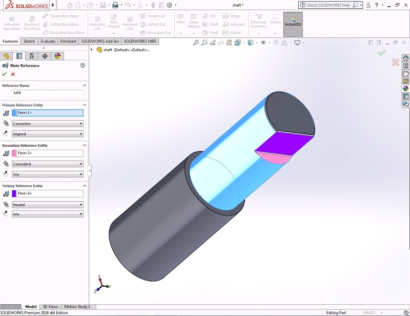
- Open the created part Shaft. Click “Mate Reference”. Under Reference name type MTR. Under Primary Reference Entity select the cylindrical face of shaft, type of mate as Concentric and select Aligned for orientation of the mate created. Under Secondary Reference Entity select the smaller D-face of shaft, type of mate as Coincident and select Any for orientation of the mate created. Under Tertiary Reference Entity select the planar face of shaft, type of mate as Parallel and select Any for orientation of the mate created.
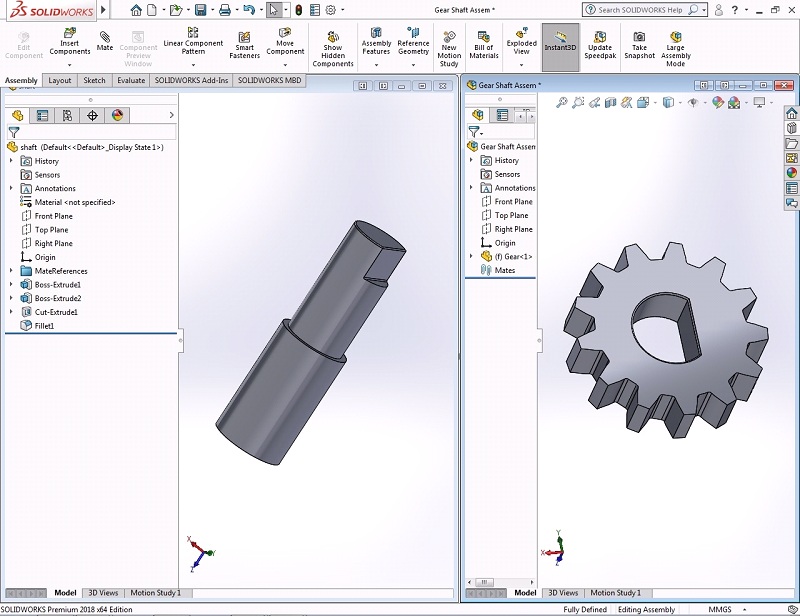
- Now the parts are ready for mating. Open the Assembly template. Click Insert Component and open the gear part by clicking browse button and locate it at the origin of assembly. Now cascade the tiles vertically and you can see both the assembly and the shaft part. Drag and drop the shaft into assembly. The shaft directly assembles with the gear as per our required mating conditions.
- The three mates have automatically been added between the two components, making use of all the references in the named Mate Reference feature.
- Save and Close all files.
