What This Warning Really Means?
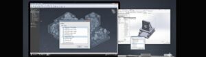
If you have ever run an internal flow in SOLIDWORKS Flow Simulation using fans, chances are you have seen this message pop up.
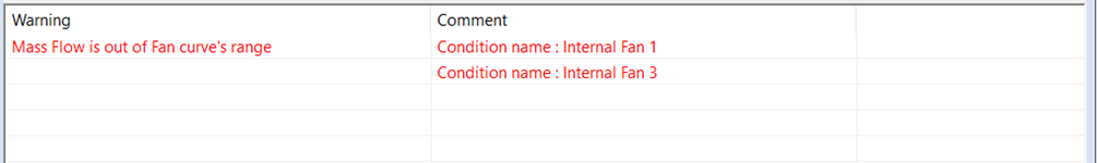
“Mass Flow is out of Fan Curve’s Range”
The solver keeps running and the result is generated. But the warning just stays there… quietly making you question everything.
I ran into this issue myself and initially did what most of us do-
- Double-checked the fan curve
- Checked the fan direction
- Rebuilt the study
- Simplified geometry
Yet the warning refused to go away.
Only after understanding how SOLIDWORKS Flow Simulation treats a fan did the problem finally make sense.
This blog shares that learning so you do not have to go through the same confusion.
First Things First: This Is Not a “Fan Curve Error”
When you see this warning, the immediate reaction is-
“Something is wrong with my fan curve.”
Most of the time, that is not true.
The fan curve itself is usually fine.
The real problem lies in how the solver is calculating pressure around the Fan. To understand that we need to talk about fan operating points.
How a Fan Works Inside SOLIDWORKS Flow Simulation
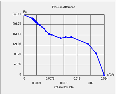
A fan curve is just a relationship between:
- Pressure difference across the fan
- The Flow rate the fan can deliver
In SOLIDWORKS Flow Simulation, that pressure difference is calculated as-
ΔP= P static, outlet − P total, inlet where,
- ΔP = Fan pressure rise
- Pstatic, outlet = Static pressure at the fan outlet
- Ptotal, inlet = Total pressure at the fan inlet
Here’s the important part-
Flow Simulation does not force the Fan to operate at a fixed flow rate.
Instead, it-
- Look at the pressure field around the Fan
- Calculates how much resistance the system is offering
- Finds a flow rate where the fan curve and the pressure field agree
That intersection is called the fan operating point. If that operating point falls outside the defined fan curve, you get the warning.
So, Why Does the Fan Operating Point Go Out of Range?
This is where things get interesting. Firstly, Mesh Quality
around the Fan In my case — and in most cases — the issue
came down to mesh density near the fan.
When the mesh is coarse:
- Pressure gradients are not captured properly
- Inlet or outlet pressures fluctuate
- The solver temporarily predicts unrealistic pressure values
As a result, the Fan appears to be operating at a flow rate that
does not exist on the curve. This is not physical behaviour — it is
a numerical artifact more of an in-software value or virtual, not
real life.
Second, Very Low Flow Resistance
If the flow path is very open and unrestricted:
- The Fan tries to push a lot of air
- The predicted flow rate can exceed the curve limits
This happens often in:
- Simplified internal models
- Early design concepts
Enclosures with large openings
Third, Outlet Pressure Drops Below Atmospheric
During early solver iterations, the pressure on the outlet side of the Fan can temporarily drop below atmospheric pressure.
When that happens:
- The operating point shifts into the negative side of the curve
- The solver flags the warning
Again, this is usually temporary and numerical.
And finally,
Fan Geometry That Looks Right—but Isn’t
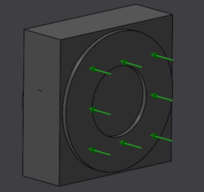
For axial fans-
- A small protrusion for the hub
- A lip around the outer diameter
- Annular, planar faces for the fan definition are required.
If the Fan is represented only using split lines on a flat face, the solver
struggles to compute pressure correctly.
Visually, it looks fine — numerically, it is not.
Why Only Some Fans Show the Warning
Another confusing aspect is when:
- Multiple fans use the same fan curve
- Only one or two fans show the warning
This is completely normal.
Each Fan sees:
- Different local geometry
- Different nearby obstructions
- Different pressure fields
Therefore, each fan finds its own operating point, even if the curve is identical.
What Actually Fixed the Problem?
After understanding the root cause, the solution became very simple-
Step 1- Fix the Fan Geometry
- Added small protrusions for hub and outer diameter
- Avoided flat, split-line-only fan definitions
This alone improved pressure stability.
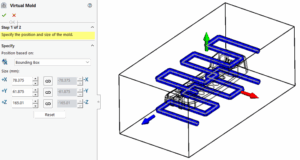
Step 2- Refine the Mesh Where It Actually Matters
This was the key change.
Refining the mesh-
- At the fan inlet
- At the fan outlet
You can do this by-
- Applying a local mesh to the fan faces, or
- Creating a local mesh region around the Fan
Both methods work.
What matters is that the pressure field near the Fan is resolved properly.
Step 3- Check the Fan Operating Point
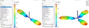
Instead of guessing, I plotted the fan operating point.
Once the mesh is refined:
- The operating point moved inside the fan curve
- The warning disappeared
- Results stabilized
This is the single best way to confirm that the fan is behaving correctly.
So, the important question, Should You Ignore This Warning?
“No” Even if the solver completes-
- Airflow values may be unrealistic
- Cooling performance may be mis–predicted
- Temperature results may look “okay”, but may be wrong
Once the warning is resolved-
- Pressure fields stabilize
- Fan behaviour becomes physically meaningful
- You can trust the results
Final Takeaway
“Mass Flow is out of Fan Curve’s Range” does not tell you your fan is wrong but rather it tells you the solver cannot accurately determine the fan’s operating point.
In most cases:
- The fan curve is correct
- The physics is correct
- The mesh near the Fan is not
Refine the mesh, model the Fan properly, and always verify the operating point. Once you do that, this warning goes from being mysterious to completely logical.