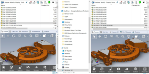
Generating terminal strip documentation is an error-prone and tedious process. Creating terminal strip drawings, cabinet layout and industrial standard charts which illustrate how the terminal strip is assembled and how the wiring is to be connected must be done to fully document a control panel. In fact, SOLIDWORKS Electrical has helpful tools that reduce this process down from hours to minutes in reducing error.
Terminal Strip Drawing in SOLIDWORKS Electrical
SOLIDWORKS Electrical has a complete terminal strip management system, from the insertion of terminals to the automatic generation of the terminal strip drawings to cabling the terminals which are included.
When you design your schematics with SOLIDWORKS Electrical, the connections to terminal strips are automatically captured using the “Insert N Terminals” option. The designer simply draws a line across the multi-wire circuit and terminal numbers that are associated with a terminal strip appear.
Initially select the terminal in the schematics in which u need to get the terminal strip drawing. Then select the command “Draw X1 terminal strip”.

And then by selecting the page of the schematics accordingly from the dialogue box, the terminal X1 drawings will be created.

Once the drawing is generated, the terminal strip drawing of terminal X1 is created in the document book. Terminal numbers can be re-assigned if needed. Another fact is that if more terminals on the same strip are added, the terminal numbers are continued.

The terminal strip contains all the connection information between the components and wires/cables and they are connected to and are managed using tools present in SOLIDWORKS Electrical.


