Finding the Natural Frequency and Mode shapes of Mechanical structures is one of the crucial considerations to avoid unknown dynamic responses due to Resonance. Resonance phenomena result in excessive vibrations and cause functional and structural failures. Because of this, it’s crucial to determine and confirm that the inherent vibration frequencies of a mechanical system are significantly higher than any potential excitation frequency that the system is expected to experience while designing it.
In my previous blog, “Frequency Analysis in SOLIDWORKS Simulation”, I mentioned about Importance of finding Natural Frequency to avoid Resonance. In this blog, I will explain the Frequency Analysis setup in SOLIDWORKS Simulation.
SOLIDWORKS Frequency Analysis is included as part of the Simulation Professional & Premium packages.
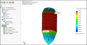
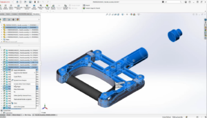
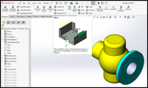
For explanation, here I’m using the following Bracket component. Bracket geometry consists of 2 holes and vertical ribs supporting a cylindrical block.

The following procedures should be followed in order to set up a frequency study in SOLIDWORKS FEA.
- Create the Model:
In SOLIDWORKS create and finalize the 3D component or Structure. You can import CAD geometry from another CAD Software.
2. Define Type of Analysis:
Set the Frequency analysis from the top left corner of the simulation tab. Frequency analysis is available only in SolidWorks Simulation Professional and Premium bundles. After choosing the Type of Analysis, Feature manager Tree will split into 2 Halves. I.e. SOLIDWORKS Feature manager Tree and Simulation Tree.

3. Set Number of Frequencies:
Right-click on the Simulation title on Simulation Tree and select “Properties”. Set the number of required frequencies in the “options” tab. The first six mode shapes or frequencies are related to free rotations (6 DOF) along XYZ directions.

To get to the first five Elastic modes of an unsupported solid model, for example, you must set the needed modes to 11, which consists of six rigid body modes and five elastic modes.
A system’s memory capacity, mesh type, geometric features, contact and connection features, and number of frequencies are all taken into consideration by the program when choosing between Intel Direct Sparse and FFEPlus Iterative as the fastest equation solver.
4. Set the Material Properties:
SOLIDWORKS has a wide range of material databases with mechanical properties which help us to do Structural Analysis. Set Material for each component in assembly or Bodies in Part.
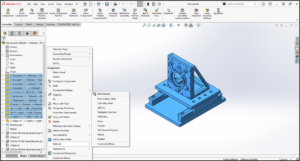
Right-click on the Component icon in the Simulation study tree and use the “Apply/Edit Material” option to access the SOLIDWORKS Default Material library and choose the Material. Or we can choose the material from the Favorite Material list.

5. Set the Load Conditions & Restraints:
You can setup Frequency analysis setup with or without loads. For frequency problems with defined loads, the Direct Sparse solver is required. Set the Restraints that the model will experience in real-world situations.

6. Create Mesh
Meshing or Discretization is a process which converts the Mathematical model into the FEA model. In SOLIDWORKS we have 3types of Basic to advance level of Mesh types. You can choose Blended curvature –based mesh or Curvature based Mesh and Set the Maximum and Minimum size of the Elements.


7. Run the Analysis: The program automatically meshes the study before running it if you run it before meshing it. You can “Run” the analysis from the Simulation Tree or Command Manger Area.

8. Evaluate the Results:
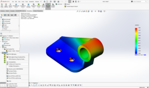
The results are shown graphically in SOLIDWORKS Simulation, together with natural frequencies and mode shapes. Right-click on “Results” and use “List Resonance Frequencies.”


To evaluate the results, compare the applied loads with the natural frequencies. Resonance is possible if the structure’s natural frequency and the applied load frequency are near to each other.
9. Change the Geometry:
We may adjust Natural Frequency and reduce vibrational response in this bracket example by changing the stiffness or by adding or subtracting mass. The structure stiffness varies depending on the geometry and material. The material’s density influences the mass of the system.
10. Rerun the Analysis:
Rerun the study once the Material and Geometry changes have been made. To further understand how the frequency causes the object to oscillate, we may animate this. We can create reports to document with all inputs (Material Information, Loads, Restraints & Meshing Information) of a study.
With the help of the above steps, we can set up Frequency Analysis in SOLIDWORKS Simulation. You can make sure that your frequency analysis prevents unintended dynamic response and design errors by making sure it is efficient & precise.

