Transformers are one of the crucial electrical components in the power sector, mainly used to convert electrical energy between different voltage levels. It is used in a wide range of applications, from large power stations to small electric chargers. This blog will provide an overview and key insights on Electromagnetic Simulation of 3-Phase Transformer using CST Studio Suite software.
Transformer simulation helps us to minimize the core material loss and to achieve better efficiency. Additionally, it will provide a detailed visualization of electromagnetic field behavior within the transformer for better design optimization and improved performance.
Modeling and Simulation of a 3-Phase Step-down Transformer using CST Studio Suite:
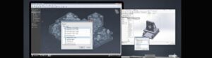
Modeling a 3-phase transformer involves creating both physical and electrical properties, as shown in Fig. 1. The model includes the transformer’s core, windings, and electrical parameters. By optimizing the transformer design, we can improve efficiency and reduce operating losses.
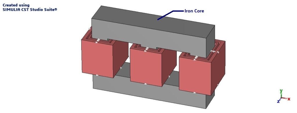
a. 3-phase Transformer Model in CST Studio Suite.
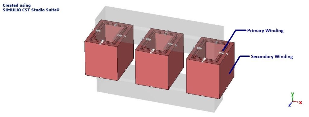
b. Primary and Secondary Windings of the 3-Phase Transformer.
Fig. 1: 3D Model of a 3-Phase Transformer in CST Studio Suite Software.
Meshing is one of the crucial steps in simulation and in this design, “tetrahedral mesh” is used to divide the transformer’s geometry into smaller elements, as shown in Fig. 2. Finer mesh elements are applied to areas with high field variations to ensure correct flux and current distribution. Regions with less field variation are applied with coarser mesh to improve computation. Mesh quality directly affects simulation accuracy and convergence; finer meshes are always good and suggested, but at the cost of high computation time.
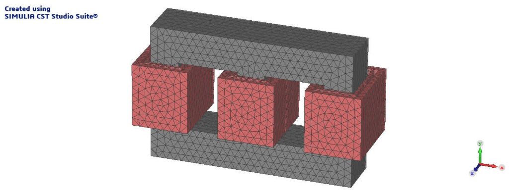
Fig. 2: Mesh Representation of a Transformer Model in CST Studio Suite Software.
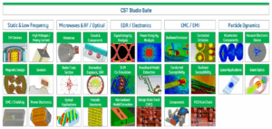
CST Studio Suite Simulation Solvers for Electromagnetic Systems and Devices. Know More…….
The simulation results of a 3-phase transformer in CST Studio Suite software offer valuable insight into performance. The voltage waveforms of both the primary and secondary windings are shown in Fig. 3, which provides a detailed voltage conversion ratio and the behavior of the transformer under different load conditions. Power losses are also calculated, highlighting the inefficiencies in the core design optimization.
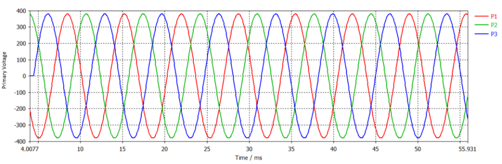
a. Primary voltage waveform of the transformer.
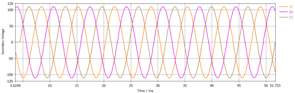
b. Secondary Voltage Waveform of the transformer

c. Ohmic losses in the transformer.
Fig. 3: Primary and secondary coil voltages, including the ohmic losses of the designed transformer.
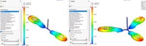
Fig. 4 illustrates the magnetic flux density (B-field) and magnetic field strength (H-field) across the core material and the windings. This aids in identifying the high flux density region, also suggesting possible saturation points in the core material and the transformer geometry.
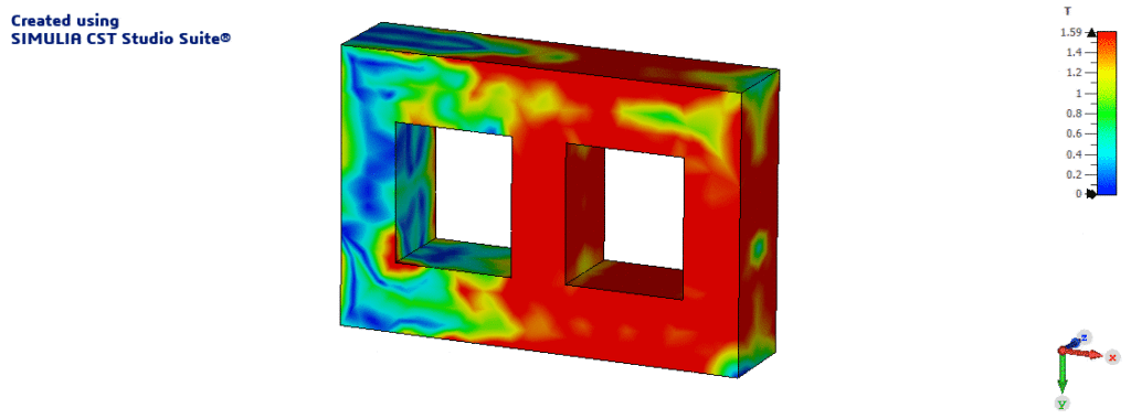
a. Distribution of B-Field
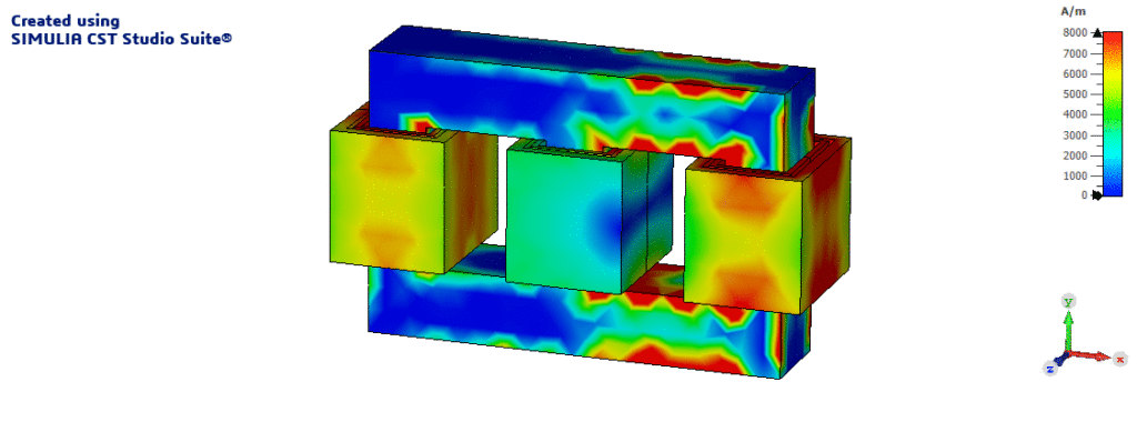
b. Distribution of H- Field
Fig. 4: Magnetic flux density (B-field) and magnetic field strength (H-field) distribution in the transformer.
CST Studio Suite is a powerful electromagnetic simulation software mainly used to design, simulate, and optimize electromagnetic components. In this case, CST Studio Suite software is used to model the transformers in detail and simulate their performance under various conditions to analyze key factors like voltage, current, magnetic flux, power loss, etc. This helps the engineers to improve the transformer designs and efficiency prior to the physical prototypes by ensuring the standards for real-world applications.
For organizations in India looking to leverage the power of CST Studio Suite for transformer design, analysis, and optimization, Conceptia Konnect stands as a leading CST Studio Suite solution provider. With our deep expertise and comprehensive support, we empower engineers to harness the full potential of CST Studio Suite to meet their specific requirements.
Unlock the power of electromagnetic simulation for your transformer designs. Contact Conceptia Konnect today for a consultation and a quotation tailored to your needs.