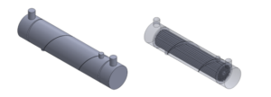
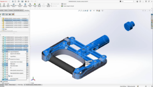
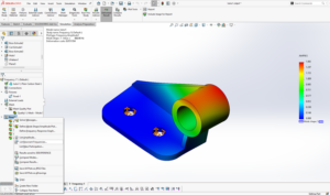
The Display of individual components in an assembly can be edited/modified by using “Components Display”. It consists of various display modes such as “Wireframe, Hidden Lines visible (HLV), Hidden Lines Removed (HLR), Shaded with Edges, Shaded, Default Display”. These display modes can be done to the Current display state, all display states, and Specified display state. This option can be found by
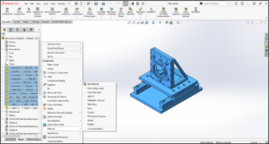
Right-Clicking on a Component(s)/Sub-Assembly(s)/Assembly.
(Or)
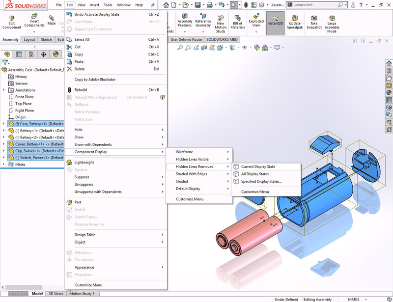
Edit > Component Display.
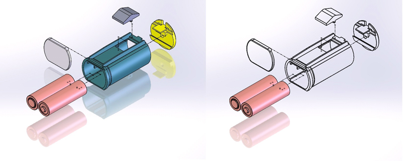
Let’s take an example of an Assembly as shown below, in which the display should be such that only the batteries should be shaded with edges and all the remaining components are in HLR display mode and the same should be used in making a drawing. Since this cannot be done directly in drawing, the component display should be modified in Assembly Modeling, to reflect it in drawing.
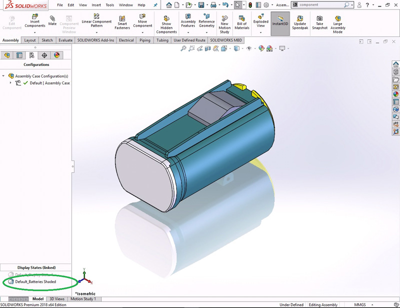
- Open an Assembly. Create an exploded view (optional). Right-Click in the Configuration Manager and click Add Display State. Rename it as Default Batteries Shaded as shown in figure. Now whatever the appearance changes that are made in this display state are not reflected in the Default_Display State-1.
- Select all the Components except the two batteries. Click Edit > Component Display > Hidden Lines Removed > Current Display State.
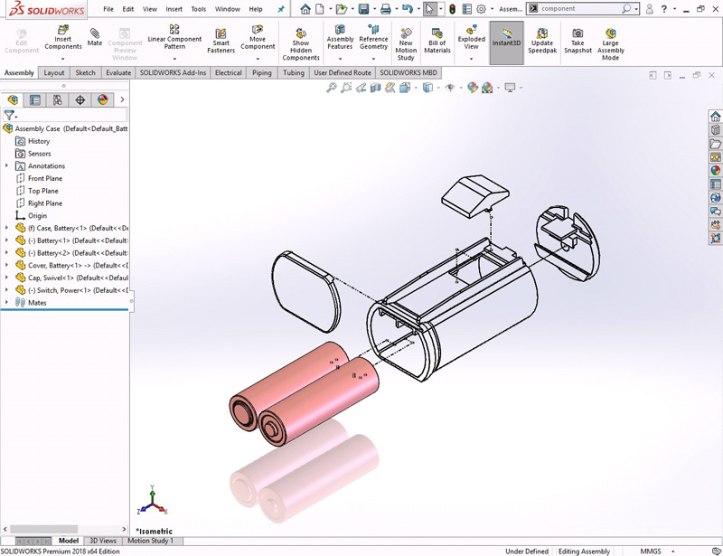
- Except the batteries, all components will be shown as below. Now it’s time to create an isometric view in drawing. Close the assembly model.
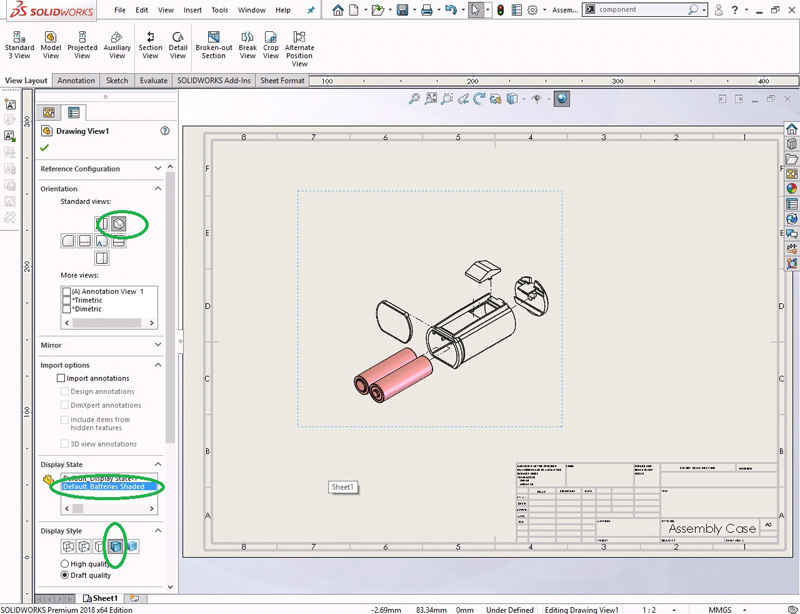
- Open a drawing template. Click on Browse and select the Assembly Case, select the display state as ‘Default_Batteries Shaded’ and click Open.
- In the property manager select orientation to Isometric, display style as Shaded with edges and position the view on the drawing sheet.
- Save and Close all files.
