In SOLIDWORKS Composer, the Digger tool is a great user-friendly tool to highlight various components in your assemblies. Just like the detail view, the Digger tool behaves like a magnifying glass to generate close-up images of your design to isolate exact areas of components you would like to display. In addition, the digger tool has a couple more functionalities which make it a powerful tool to utilize, such as the ‘X-Ray’ and ‘Onion skin’ that can generate further advanced visuals. Moreover, the digger tool offers various customization controls to ensure that you are able to create high-resolution image outputs and animations for dynamic presentation purposes.
Usage of Digger Tool in SOLIDWORKS Composer
Particularly when creating manufacturing assembly instructions or user manuals, the Digger can provide additional detail and information for your audience to use which can improve overall quality of the presentation output and also reduce documentation related issues.
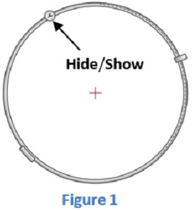
To bring the Digger into view click on the Home tab found in the ribbon, then click the digger icon. However if you prefer key-board shortcuts then press the ‘Space bar’ or ‘Ctrl D’ and it will instantly pull-up the Digger tool. The Digger icon should appear similarly as shown in figure 1. However as you can see the digger tool seem very bare, this is due to the ‘Hide/show button’ which will toggle the visibility of the additional features within Digger tool. Below is shown a full outline of the tool in figure 2.

Digger Tool Overview – SOLIDWORKS Composer
Tool | Function |
| Radius | This option enables dynamic changing of the size geometry of digger tool. |
| Percentage | Enables the adjustment of levels of a specific tool utilized. |
| Show/Hide | Toggles the visibility of the additional tool buttons. Turning the buttons off will bring a cleaner interface for the composer environment with less clutter. |
| Change center of interest | Alters the location of the target area selected. This is useful to provide focus to important areas to view. |
| Lock/Unlock Depth Direction | Locking will maintain constant digger view geometry as the model is rotated. Whereas unlocking will enable the digger view to update whist the model is in rotation. |
| Zoom | The zoom function provides magnification of a specified geometry. The intensity of the zoom can be controlled via the ‘Percentage’ handle.
|
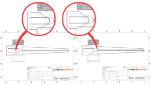
| Onion skin | This function peels away layers of geometry to visually display internal part geometry layer-upon-layer. Maximizing the ‘Percentage handle’ will strip away all layer geometry and minimizing will fully maintain model geometry. The amount of layers taken off can be specified using the percentage handle also.
|
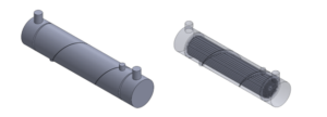
| X-Ray | This function visually suppresses layer of geometry to display internal part geometry; the suppressed layer are altered in the form of transparent ‘Ghost’ outline. Specifically the X-Ray function helps you isolate the exact areas of components you would like to have displayed, whilst maintaining external geometry in the form of ‘Ghost’ to illustrate the full-scale model geometry.
|
| Cutting plane | This tool provides an invisible flat plane which ‘cuts’ into the full model and removing any entities normal to the plane. The cutting plane is effective in regards to quickly illustrating a sectional half-cut within composer. In addition, the plane is oriented dependent on the user viewing position.
|
| Light change | The model’s lighting effects can be effectively adjusted vi this function to illuminate target areas for further clarity. Moreover a useful lighting icon is materialized for a user to manually drag the lighting direction and position.
|
| Capture Picture in 2D image | Toggling the ‘Zoom’ and ‘Change centre of interest’ can help define a desire view position, this specific view can then be captured as a 2D image. Upon creation of the 2D image-composer will also conveniently produce a leader arrow which will point to an area of origin. Top tip: the below image displays two 2D captures the wheel of the model. Typically the 2D image capture will be outputted with a low resolution image which can provide a bad quality capture. To generate a higher quality output the image resolution can be adjusted by clicking the ‘Workshop tab > Publishing > High resolution image’ following this – the pixel, dpi and jpeg quality setting can be adjusted to the desired setting. The difference of the image quality can be shown in the blow illustration. In addition, it is recommended to save the profile of the setting to re-utilize the setting to save the need to re-enter the option.
|
Thank you for taking your time to read my blog and I hope you have enjoyed following my summarized Digger tool overview. It is hoped that the tool outline can be applied to your personal work and be useful to build upon your SOLIDWORKS knowledge.


