2D Footprint in SOLIDWORKS Electrical
In Electrical design the electrical cabinet creation plays a vital role, Now SOLIDWORKS Electrical makes this job so easier by its unique successful approach in electrical design
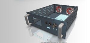
Normally while creating electrical cabinet, electrical components are focused but at the same time mechanical components in cabinet is also important because the arrangement and supporting structures are important in real time implementation of the electrical cabinet.
Electrical cabinet contains both electrical and mechanical components, so we can expect both mechanical – electrical collaborated Bill of material.
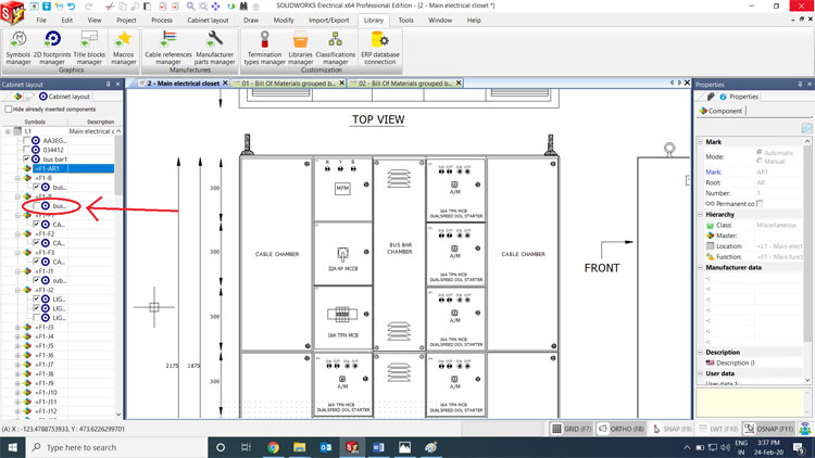
SOLIDWORKS Electrical is a dedicated tool for cabinet creation where it has separate graphic zone for such works.
We can create our own custom parts and can use in various projects.
Basically we can create Cabinet related component library in 2D Footprints library
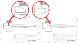
Where we can create both mechanical and electrical components with exact predefined dimension, so that’s how SOLIDWORKS Electrical makes GA drawing simple.
Step 1 – Open 2D Footprints library

Step 2 – Select the class based on electrical component. Select the class miscellaneous to add mechanical components. Then click new

Step 3 – Give the details of the symbol with manufacture details if needed

Step 4 – Create the component or symbol and define the dimension if we create mechanical component.

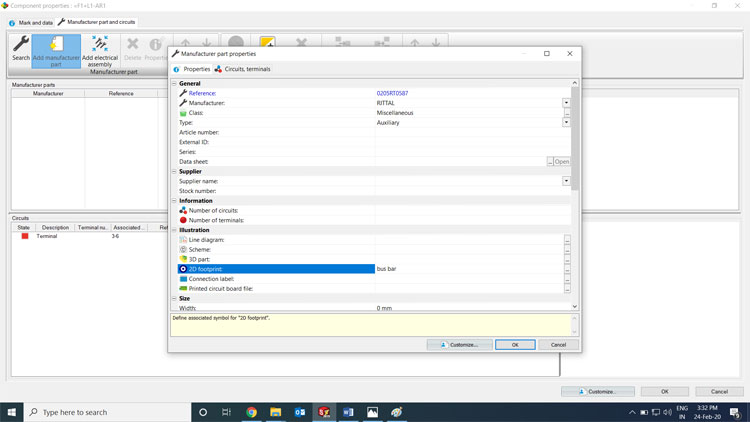
Step 5 – After creation of the component then associate that symbol with respected components in cabinet layout tab.


Give the details of the manufacturer, In illustration tab select 2D footprint and select the newly created footprint and click OK.
Step 6 – Selected the component and place it GA drawing on defined location
