In Layout-based Assembly Design in SOLIDWORKS, you can switch back and forth between top-down and bottom-up design methods. You can create, edit, and delete parts and blocks at any point in the design cycle without any history-based restrictions. This is particularly useful during the conceptual design process, when one frequently experiments with and makes changes to the assembly structure and components.
To Create a Layout-Based Assembly Design in SOLIDWORKS:
- Open a new assembly.
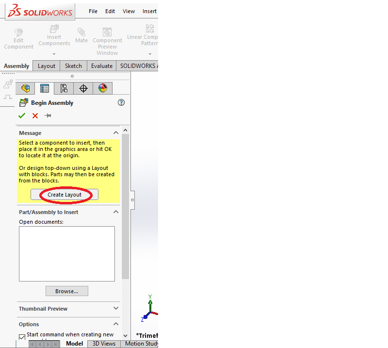
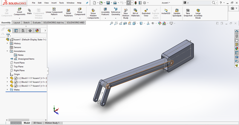
- In the Begin Assembly Property Manager, click Create Layout . A 3D sketch opens, and layout appears in the Feature Manager design tree.
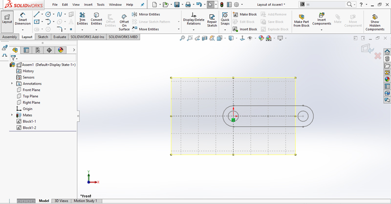
- Create sketch entities and group related entities into block and close the sketch.
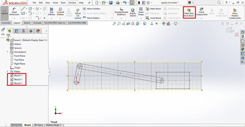
- Similarly, the same procedure is performed for creating the remaining blocks.
Make Part from Block Property Manager
In assemblies, you can create parts from blocks in layout sketches.
To create a part from block:
- Click Make Part from Block
 (Layout Tools toolbar).
 - Select one or more blocks from the layout sketch.
- Make selections in the Property Manager as described below.
- Click
Selected Blocks
![]() Selected Blocks list the blocks that one selects.
Selected Blocks list the blocks that one selects.
Block to Part Constraint
![]() Creates a part that is projected from the plane of the block in the layout sketch, but not constrained to be coplanar with it.
Creates a part that is projected from the plane of the block in the layout sketch, but not constrained to be coplanar with it.
![]() Constrains the part to be coplanar with the plane of the block in the layout sketch.
Constrains the part to be coplanar with the plane of the block in the layout sketch.
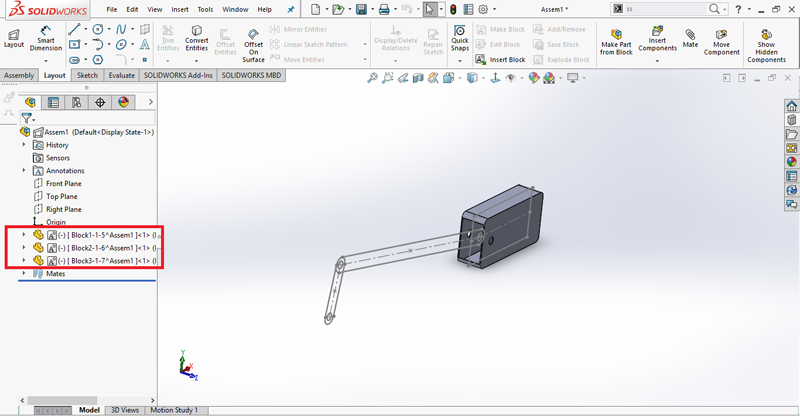
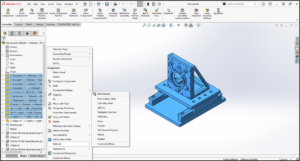
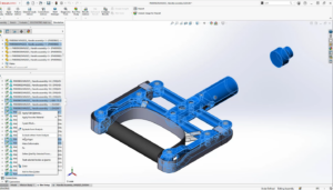
After creating part, right click on the part in the Feature Manager design tree and click open part. Part workbench is opened and select Extrude Boss/Base and select the sketch.

Similarly, the same procedure is performed for remaining parts.
