Imagine a component or Mechanical Structure that behaves in the same way along a specific plane or axis. Instead of analysing the entire component or every single part in the model, you can solve for a partial model and extend the results to a complete model using Symmetry Fixtures in SOLIDWORKS Simulation. Analysing symmetrical models in SOLIDWORKS Simulation can be a highly effective approach to reduce computation time and improve efficiency while ensuring accurate results.
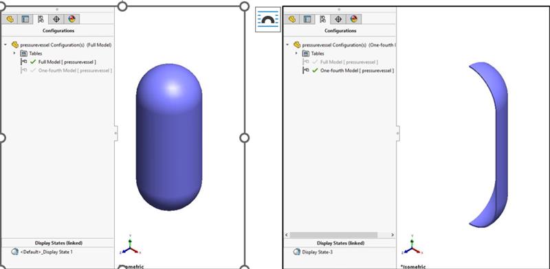
To illustrate, consider simulating a cylindrical pressure vessel with symmetric geometry, instead of modelling the entire vessel, you can model just one section (for example, one-fourth of the full model) and apply symmetry boundary conditions along the faces. The results of one section can be implied to complete the model.
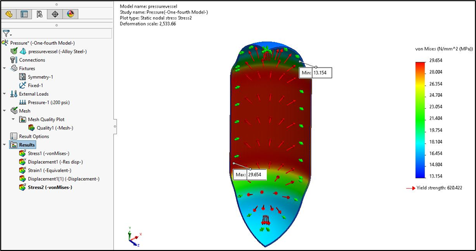
Example: Consider a pressure vessel made up of Alloy Steel experiencing 200 psi pressure on the internal faces. The stresses developed on the vessel can be determined only by using one-fourth of the model due to its symmetric geometry.
The stages in analysing the pressure vessel are as follows:
1. Preparing the Model:
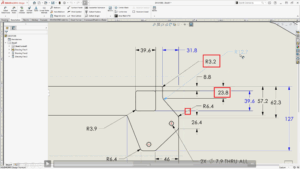
As the pressure vessel is symmetric to the axis, a new configuration named One-fourth Model is created with one-fourth of the model. In this specific case, one eight of the models could also be considered.
2. SOLIDWORKS Simulation Options:
You can customize Simulation software to reflect the standards your company uses for analysis prior to the study using the Options dialogue box available under the simulation menu tab.
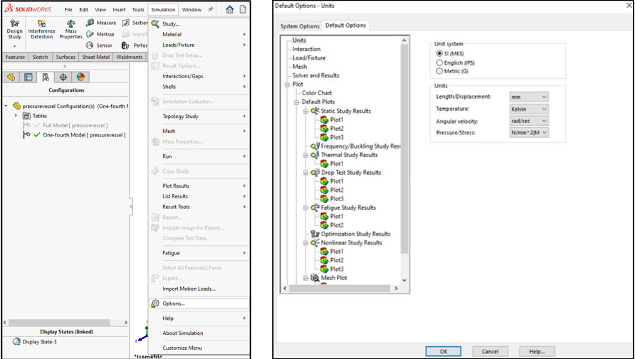
For this study, the global system of units is set to SI (MKS).
3. Creating the study:
Create the study using the New Study command available under the Simulation tab on the CommandManager. If the Simulation tab is not visible on the CommandManager, enable SOLIDWORKS Simulation under SOLIDWORKS Add-Ins.
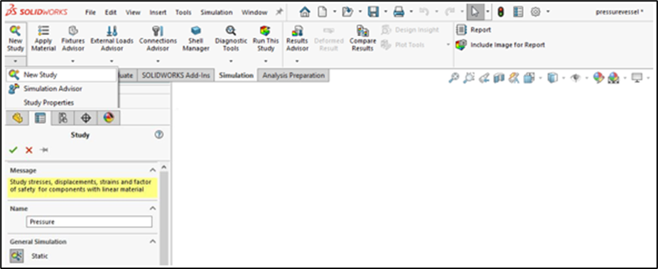
SOLIDWORKS Simulation offers a diverse range of study types, which are tailored to different engineering challenges, including static analysis, thermal analysis, motion simulation, and more. A static study was selected to analyze the stresses and deformation in the pressure vessel, and the new study was named Pressure.
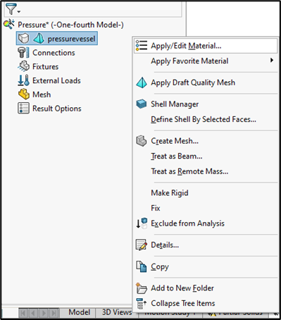
4. Assigning Material Properties:
SOLIDWORKS provides a standard material database, which has a collection of predefined material properties and essential data such as mechanical, thermal, and physical properties.
If the material is already defined during modelling, the information will be transferred automatically into SOLIDWORKS Simulation. You can also assign the material properties to the bodies in the SOLIDWORKS Simulation window using the Apply/Edit Material or Apply Favorite Material window.
In this study, the material Alloy Steel is assigned to the pressure vessel using the Apply/Edit Material window.
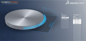
5. Defining Symmetry Restraints:
In any Simulation study, it is essential to apply the boundary conditions to the model since they help define the movement or deformation of the model under the applied loads and model interaction with the environment.
SOLIDWORKS Simulation provides various fixtures that can be used to restrain the model. For the models with identical geometries, you can simulate only part of a symmetrical object while assuming that the rest of the object behaves similarly using the Symmetry fixture.
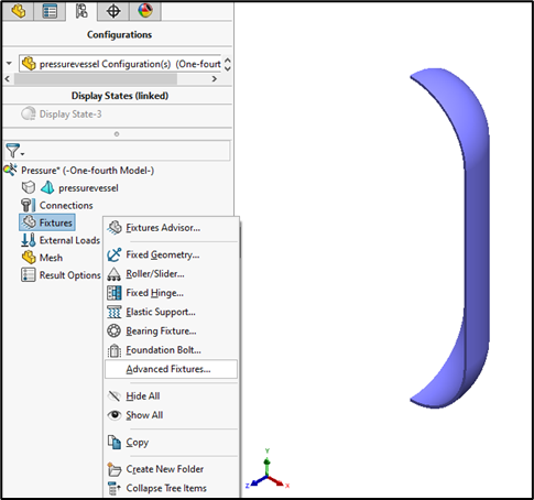
To access the Symmetry Fixture, right-click Fixtures and select Advanced Fixtures. In the PropertyManager, choose Symmetry under the Advanced option and select the faces of Symmetry for Planar Faces for Fixture in the graphics area.
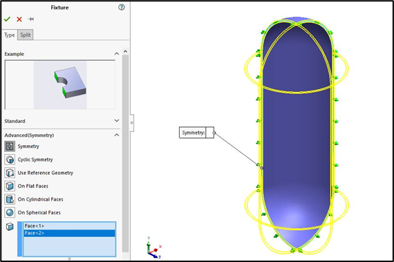
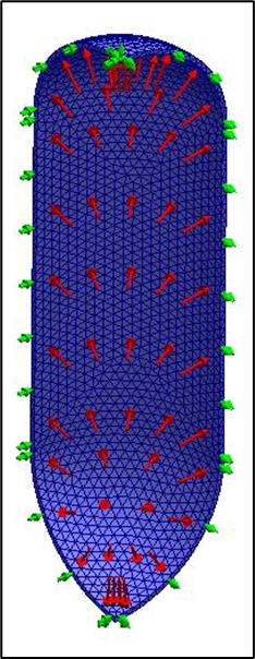
One-fourth of the pressure vessels considered in this study selected radial faces to make the model act as complete vessels.
6. Stabilizing the Model:
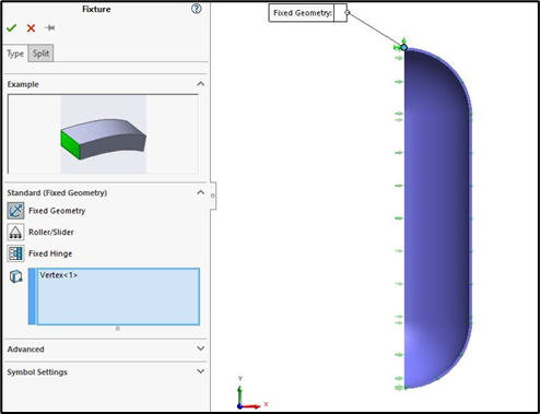
With the Symmetry restraints applied, the model can still move in the axial direction. To eliminate the motion in the model, it is enough to restrain just one vertex of the component. Alternatively, the Soft Springs feature can be used to remove the motion in the models.
To stabilize the model, Right-click on the Fixtures and select Fixed Geometry. In the PropertyManager, select the vertex as shown below for Faces, Edges and Vertices for Fixture.
7. Applying Loads:
In SOLIDWORKS Simulation, forces or constraints are applied to a model to simulate real-world conditions. These loads are critical in determining how a part or assembly will behave under certain conditions, such as stress, strain, and displacement.
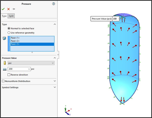
SOLIDWORKS Simulation provides various types of loads such as force, pressure, gravity and more. You can access the different types of loads by using the External Loads command available in the SOLIDWORKS Simulation window.
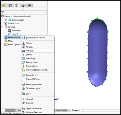
In this case, a Uniform Pressure of 200 psi is applied on the internal surface of the pressure vessel.
8. Mesh and Run:
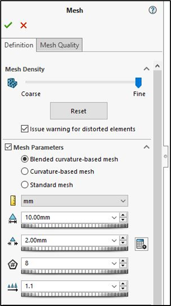
A Mesh is a collection of small, simple geometric shapes that divide the part or assembly into smaller sections for numerical analysis. You can choose the type of mesh and mesh parameters based on your application using the Create Mesh command.
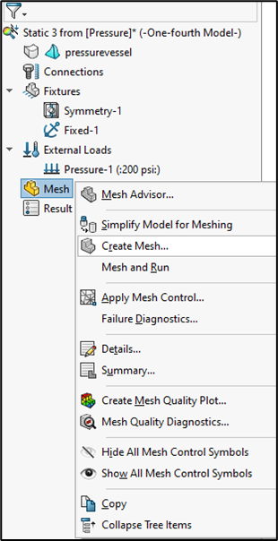
Run the analysis using the Run command.
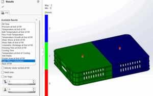
9. Plotting the Results:
Even though the analysis is performed on only a fraction of the model, the results are for the whole model, based on symmetry assumptions.
By default, stress, displacement, and strain plots will be available in the results. You can also plot the various results, such as equivalent stresses, factors of safety, and more, as per your requirement. You can also modify the representation of the results, such as units, number format and decimal places, by using the Edit Definition option.
Ultimately, symmetry analysis helps streamline the design and testing process, especially for large or repetitive structures, helping the users achieve speedy, reliable simulations without sacrificing accuracy.
For any new requirement for CAD/CAM/CAE contact us at [email protected] and phone at 9590506408.
For further assistance and support, you can contact Conceptia Konnect through mail at [email protected] or toll-free number 1800-425-8959.