A design table is a handy tool available in SOLIDWORKS for creating configurations of the components using an Excel sheet. The Design table is easy to use since it can utilize the Excel sheet functionalities. For configuring non-Hole wizard holes in a part using the Design table, the dimensions of the holes i.e., the address of the diameter and depth dimensions can be added in the design table header and hence the different hole sizes can be created. In the case of the hole wizard holes, since, the sizes of the holes are pre-defined in the toolbox, the different configurations (hole sizes) can be accessed in a Design table by using the proper syntax of the address in the column headers.
Creating the Configurations using the design table:
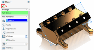
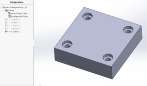
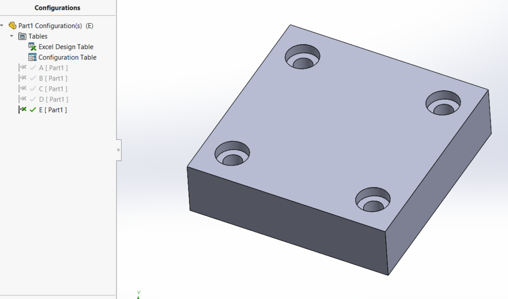
In this example, I am considering a block consisting of 4 equal-sized counterbore holes. The block consists of 5 different configurations: A, B, C, D and E. Each configuration consists of different hole sizes created using the Hole Wizard feature.
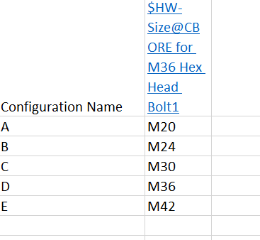
A design table has been used to configure the blocks, with each configuration having a different hole- size. The table below shows the mapping of the block configurations with the hole sizes.
| Sl.No. | Configuration Name | HW-Hole Size |
| 1. | A | M20 |
| 2. | B | M24 |
| 3. | C | M30 |
| 4. | D | M36 |
| 5. | E | M42 |
Accessing the Hole Wizard Hole Sizes in the Design table:
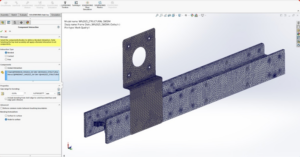
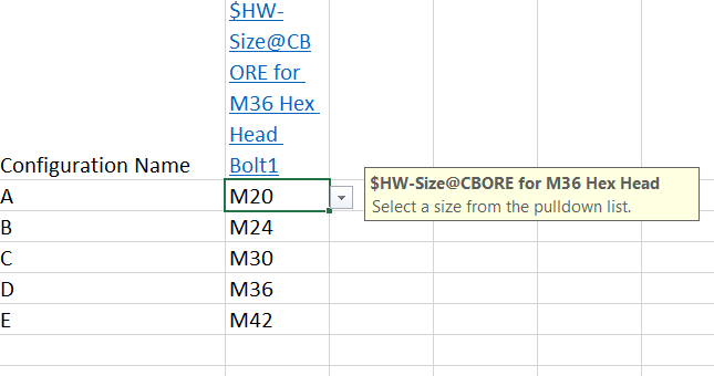
To assign the different hole sizes for the different configurations in the design table, the column header $HW-Size@ Hole feature name, as shown in the feature manager tree, is to be added. For example, for adding the column header for a M36 hole size in the design table, the syntax should be written as: $HW-Size@CBORE for M36 Hex Head Bolt1.
After adding the column header in this manner, the design table to be closed and reopened to select the different sizes of the holes for each configuration from the drop-down.
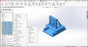
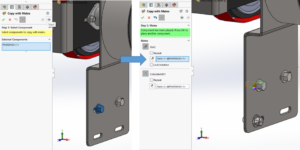
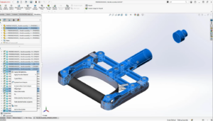
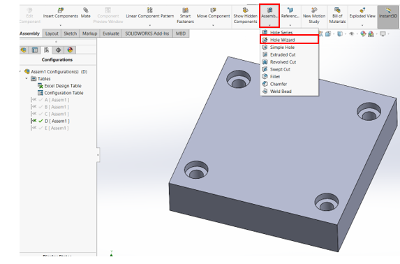
With the hole-sizes selected, the design table is to be closed to reflect the changes in the 3D CAD model. In the assemblies, to add the HW-hole size configurations, the standard hole is to be created from the Hole-wizard feature available inside the assembly features as shown below.
Conclusion:
By using the proper format of the column headers in the Design table, it is possible to easily access the standard hole configurations both in the part and assemblies created using the Hole wizard features. Stay connected with the Conceptia KonnectBlogs for more useful tips concerning SOLIDWORKS and 3DEXPERIENCE Solutions. For any new SOLIDWORKS requirement mail at [email protected] or call to 9590506408.