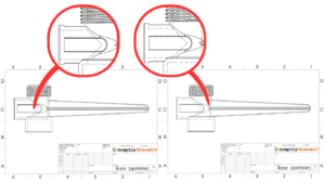
Weld beads are usually added to parts or assemblies to convey the information to the production team and this weld bead is also reflected in the drawings.
The Weld Beads also show how the parts/assembly will look once it is being weld.
Adding Weld Beads in SOLIDWORKS
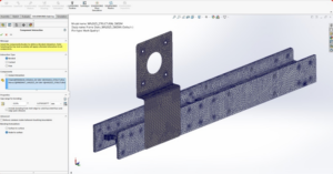
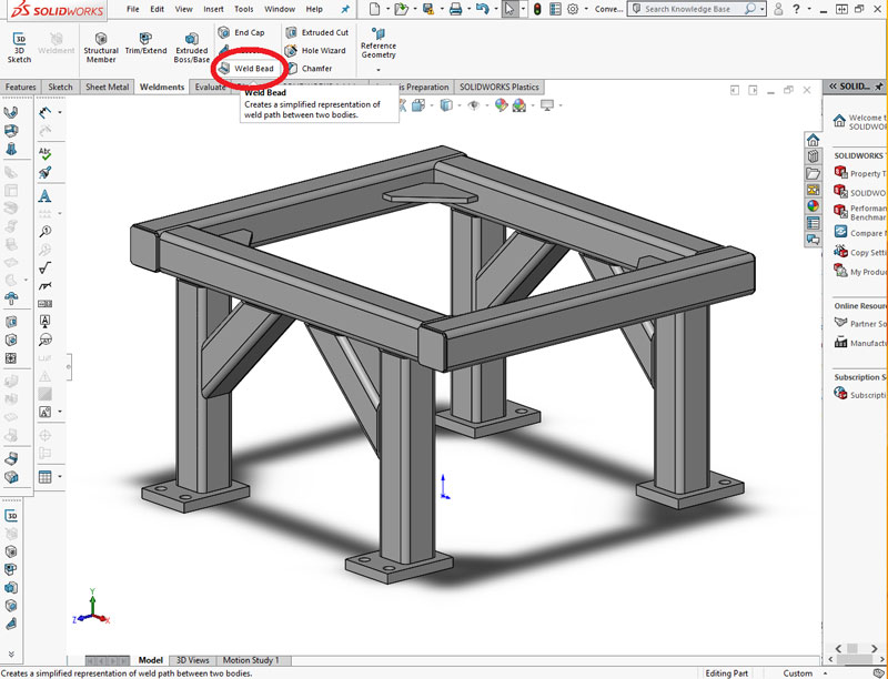
Let’s add a weld bead to a conveyor frame assembly in SOLIDWORKS which is being designed using weldments. First create a conveyor frame using weldments.
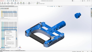
- Open the created part and select Weld Bead from the weldments section. The weld bead dialogue box appears in the property manager tab.
- The weld selections can be done in two ways
- Weld Geometry: In this option select the faces to be weld. First select the face to weld from and then select the face to weld to. Then specify the diameter of the weld. Three options are available for selecting both sides, all around and only for the selection. If tangent propagation is enabled then all the edges tangent to the faces selected will be welded.
- The weld selections can be done in two ways
In this example tangent propagation and selection is selected

- Weld Path: In this option the edges to be weld are selected and then the diameter of weld is specified. In this example all the 8 edges are selected and the radius of weld is set as 3mm.
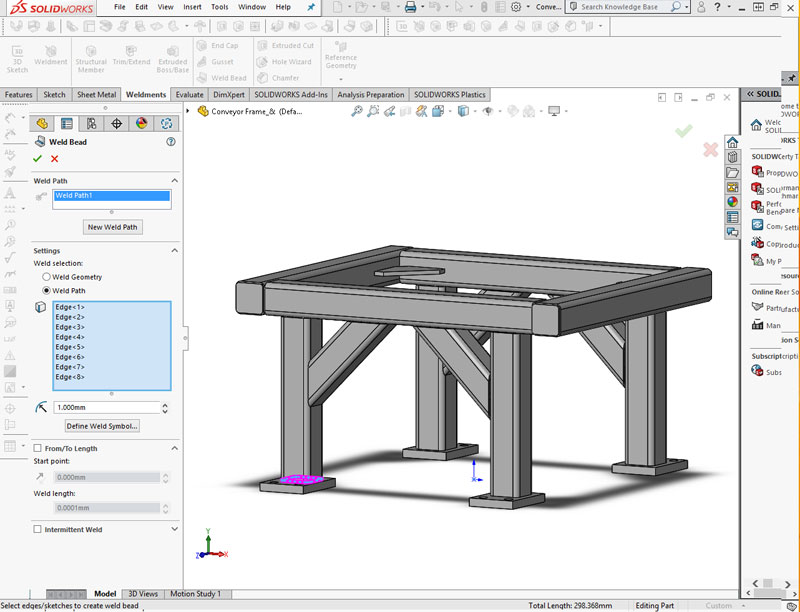
- More Options:
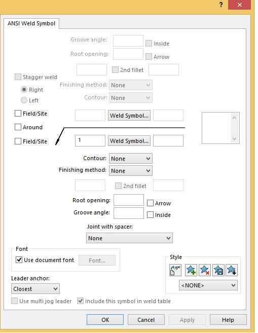
- Define Weld Symbol: The type of weld can be defined in this option. Different weld symbols can be used as well as the groove angle of weld and other parameters can be set.
- More Options:
- From / To Length: The length of the weld bead can be specified in this option by giving the start point of the weld and the weld length.
- Intermittent Weld: In this option intermittent welds can be created (patterned or staggered). The inputs are given either of the two ways.
- Gap and weld length
- Pitch and weld length
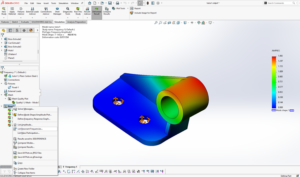
- The weld bead is created and can be done to other parts also.
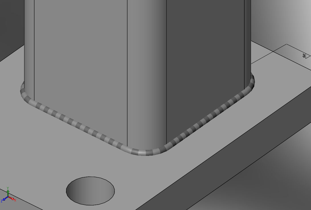
3. Save and Close all files.

