Surface Modeling in SOLIDWORKS
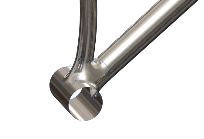
In the next step by step we will see how the Surface Coating tool is used to soften the nodes of a bicycle frame.
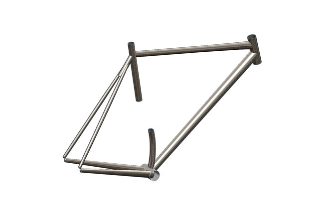
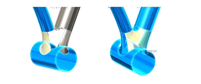
To begin, we will look at the lower node and follow the next steps.

- Trimming the upper tubes.
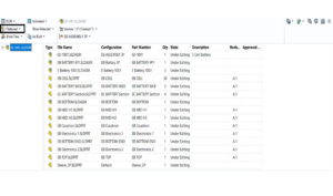
To start we will prepare the tubes to be able to make the desired coating. First, we hide the surfaces we don’t need to make the job easier.
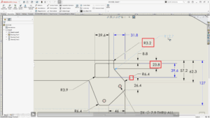
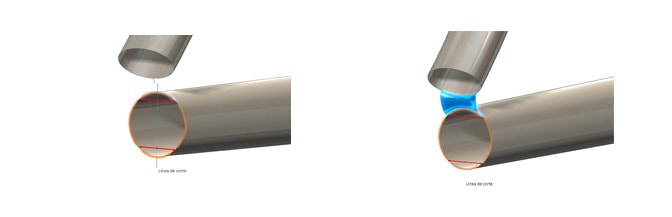
We create a sketch in the lateral plane. The lines that will cut the tubes are drawn, and segmented with the “Split Entities” tool. The arrows in the image indicate the partitions made. We cut the tubes with the sketch using “Trim Surfaces”.

- Segment the cut lines.
The partitions in the cutting line will make the section of the tube split into four curves instead of a complete circumference, as seen in the image. This will allow us to create surfaces from four different profiles. It would not be necessary if we only had to join 2 tubes. But having a more complex node, we must create the final surface through several simpler surfaces, as shown below. In addition, if we vary the partition point in the cutting line, we will be able to vary the final shape of the surfaces. We will see the complete process of creating surfaces later.
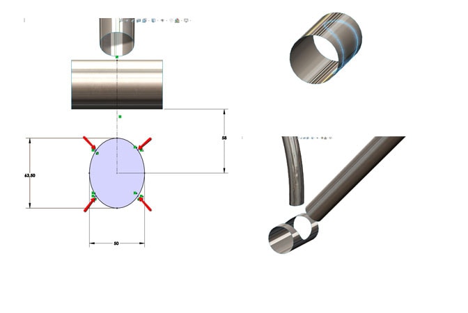
- Trim the bottom tube.
To trim the bottom tube, we will project a sketch on the surface. We create the sketch in the upper plane and draw an ellipse, splitting it into 4 as previously. Using the wrap operation, we project the sketch on the surface. We remove the face to create a hole.
- Surface creation.
We reach the key point of the exercise. We create the desired surfaces with the tool “Coating surfaces”. We can see how the segments that we have created previously in the lines of the sketches are useful now to delimit each surface.
With “Fill Surface”, we create the remaining surfaces to complete the joint. This command can be used when we already have all the edges of the new surface.
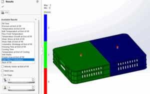
- The Result.