
When working with imported or bought out parts, we have often faced issues where the origin or coordinate the system of the part or assembly is not located in the place where we require. In this blog we will take a look at default SOLIDWORKS change origin / coordinate system.
Change Origin orientation of parts and coordinating system
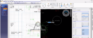
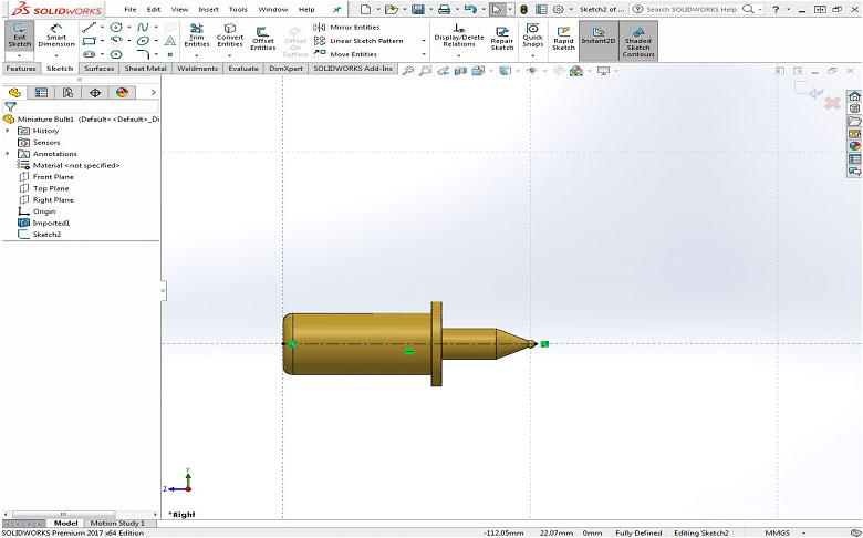
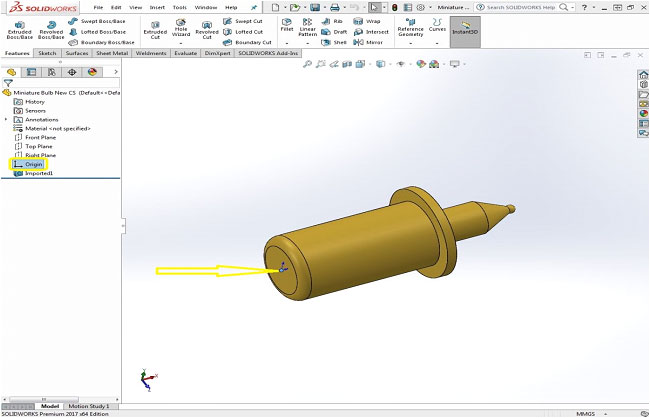
We can see in the below imported Miniature bulb part that the origin is located someplace which might not desired.
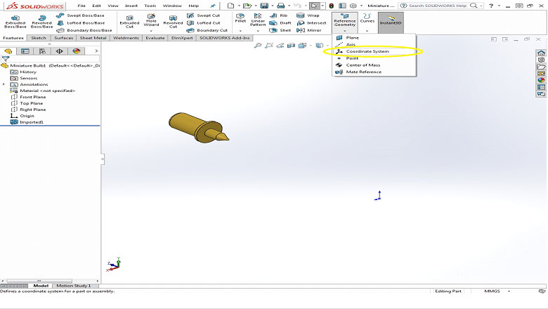
Now in order to change the co-ordinate system we have to add a new reference Coordinate System which can be added by making use of existing geometry or sketch.
Now let’s create a reference sketch to place our reference coordinate system as shown below.
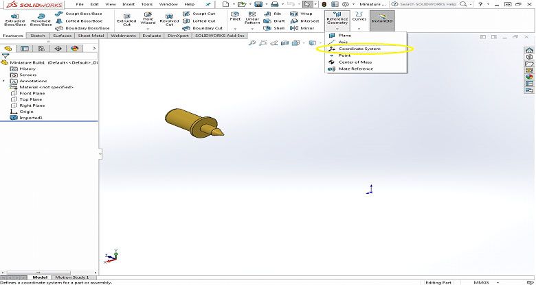
After the sketch is created, select Coordinate system from the reference geometry tab.
Now select the new origin reference and axis reference to place and position the new coordinate system as shown below. And click OK.
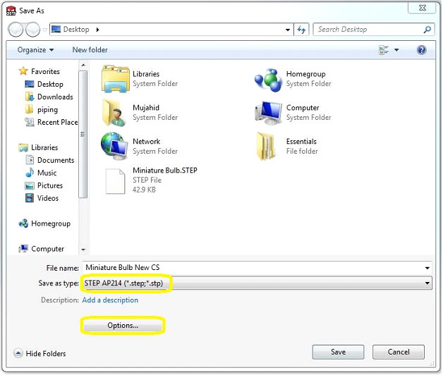
Click Save As and select the output type to neutral file format such as STEP or IGES and Select Options
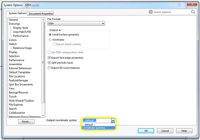
Change the Output coordinate System as shown below and click OK and save the file with a new name.
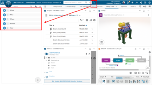
Open the newly saved file and we can see that coordinate system is changed.
Please find a YouTube video for the quick tip on Change Origin of Imported Parts in SOLIDWORKS.
Follow Us on LinkedIn